<?xml version="1.0" encoding="ISO-8859-1"?><article xmlns:mml="http://www.w3.org/1998/Math/MathML" xmlns:xlink="http://www.w3.org/1999/xlink" xmlns:xsi="http://www.w3.org/2001/XMLSchema-instance">
<front>
<journal-meta>
<journal-id>0717-5000</journal-id>
<journal-title><![CDATA[CLEI Electronic Journal]]></journal-title>
<abbrev-journal-title><![CDATA[CLEIej]]></abbrev-journal-title>
<issn>0717-5000</issn>
<publisher>
<publisher-name><![CDATA[Centro Latinoamericano de Estudios en Informática]]></publisher-name>
</publisher>
</journal-meta>
<article-meta>
<article-id>S0717-50002011000300004</article-id>
<title-group>
<article-title xml:lang="en"><![CDATA[A Discrete Event Simulation Model for the Analysis of Software Quality Attributes]]></article-title>
</title-group>
<contrib-group>
<contrib contrib-type="author">
<name>
<surname><![CDATA[Bogado]]></surname>
<given-names><![CDATA[Verónica]]></given-names>
</name>
<xref ref-type="aff" rid="A01"/>
</contrib>
<contrib contrib-type="author">
<name>
<surname><![CDATA[Gonnet]]></surname>
<given-names><![CDATA[Silvio]]></given-names>
</name>
<xref ref-type="aff" rid="A01"/>
</contrib>
<contrib contrib-type="author">
<name>
<surname><![CDATA[Leone]]></surname>
<given-names><![CDATA[Horacio]]></given-names>
</name>
<xref ref-type="aff" rid="A01"/>
</contrib>
</contrib-group>
<aff id="A01">
<institution><![CDATA[,Consejo Nacional de Investigaciones CientÃ­ficas y TÃ©cnicas (CONICET).  ]]></institution>
<addr-line><![CDATA[Santa Fe ]]></addr-line>
<country>Argentina</country>
</aff>
<pub-date pub-type="pub">
<day>00</day>
<month>12</month>
<year>2011</year>
</pub-date>
<pub-date pub-type="epub">
<day>00</day>
<month>12</month>
<year>2011</year>
</pub-date>
<volume>14</volume>
<numero>3</numero>
<fpage>4</fpage>
<lpage>4</lpage>
<copyright-statement/>
<copyright-year/>
<self-uri xlink:href="http://www.scielo.edu.uy/scielo.php?script=sci_arttext&amp;pid=S0717-50002011000300004&amp;lng=en&amp;nrm=iso"></self-uri><self-uri xlink:href="http://www.scielo.edu.uy/scielo.php?script=sci_abstract&amp;pid=S0717-50002011000300004&amp;lng=en&amp;nrm=iso"></self-uri><self-uri xlink:href="http://www.scielo.edu.uy/scielo.php?script=sci_pdf&amp;pid=S0717-50002011000300004&amp;lng=en&amp;nrm=iso"></self-uri><abstract abstract-type="short" xml:lang="en"><p><![CDATA[Abstract A discrete event simulation model for evaluating quality attributes, employing the software architecture, is proposed in this work. A metamodel of the software architecture domain that includes the concepts required for measuring quality attributes at runtime is specified. So, a simulation model is built from it, following the principles of hierarchy and modularity, assembling simple blocks to obtain complex blocks. DEVS framework is applied to obtain a decoupled model from the simulator, and the DEVS formalism is used to specify the elements of the simulation model. The objective of this approach is to provide information about the quality attributes that can be measured at runtime, introducing the discrete event simulation in the context of the software architecture design. This quantitative information will assist the architect to make decisions about the design of the system. Resumen: Un modelo de simulación por eventos discretos para la evaluación de atributos de calidad, a partir de la arquitectura del software, es presentado en este trabajo. Inicialmente, se especifica un metamodelo del dominio arquitectónico que incluye los conceptos necesarios para medir atributos de calidad en tiempo de ejecución. A partir del mismo, se construye un modelo de simulación siguiendo los principios de jerarquÃ­a y modularidad, ensamblando bloques simples para obtener bloques más complejos. La aplicación del framework DEVS permite obtener un modelo desacoplado del simulador, y el formalismo DEVS permite especificar los elementos de dicho modelo de simulación. El objetivo de la propuesta es proveer información sobre atributos de calidad que puedan ser medidos en tiempo de ejecución, introduciendo la simulación por eventos discretos en el contexto del diseño de arquitecturas de software. Esta información cuantitativa permitirá al arquitecto tomar decisiones sobre el diseño del sistema.]]></p></abstract>
<kwd-group>
<kwd lng="en"><![CDATA[Quality Attribute]]></kwd>
<kwd lng="en"><![CDATA[Software Architecture]]></kwd>
<kwd lng="en"><![CDATA[DEVS]]></kwd>
<kwd lng="en"><![CDATA[Simulation Model]]></kwd>
<kwd lng="es"><![CDATA[Atributo de Calidad]]></kwd>
<kwd lng="es"><![CDATA[Arquitectura de Software]]></kwd>
<kwd lng="es"><![CDATA[DEVS]]></kwd>
<kwd lng="es"><![CDATA[Modelo de Simulación]]></kwd>
</kwd-group>
</article-meta>
</front><body><![CDATA[ <div type="HEADER">            <p align="center"><font face="Verdana" size="2">    <br>         </font>         </p>              <p style="margin-bottom: 0.89cm;" align="left" lang="en-US"> <font face="Verdana" size="2">    <br>         </font>         </p>       </div>            <p style="margin-left: 0.5cm; text-indent: -0.5cm; line-height: 0.64cm; widows: 2; orphans: 2;" align="center" lang="en-US">  <font size="5" face="Verdana"><b><font size="4">A Discrete Event Simulation               Model for the Analysis of Software Quality Attributes</font></b></font></p>            <p style="font-style: normal; widows: 2; orphans: 2;" align="center" lang="en-US">       <font face="Verdana" size="2">           <br>         </font>       </p>            <p style="widows: 2; orphans: 2;" align="center" lang="en-US"> <font size="2" face="Verdana"><span style="font-style: normal;"><b>Ver&Atilde;&sup3;nica Bogado, Silvio               Gonnet, Horacio Leone</b></span></font></p>            <p style="font-style: normal; widows: 2; orphans: 2;" align="center" lang="en-US">       <font face="Verdana" size="2">           ]]></body>
<body><![CDATA[<br>         </font>       </p>            <p style="widows: 2; orphans: 2;" align="center" lang="en-US"> <font size="2" face="Verdana"><span style="font-style: normal;">INGAR, Instituto de             Desarrollo y Dise&Atilde;&plusmn;o (UTN-CONICET),</span></font></p>            <p style="widows: 2; orphans: 2;" align="center" lang="en-US"> <font size="2" face="Verdana"><span style="font-style: normal;">Santa Fe, Argentina, 3000</span></font></p>            <p style="widows: 2; orphans: 2;" align="center" lang="en-US"> <font size="2" face="Verdana"><i>{<a href="mailto:vbogado@santafe-conicet.gov.ar">vbogado</a>,             <a href="mailto:sgonnet@santafe-conicet.gov.ar">sgonnet</a>, <a href="mailto:hleone@santafe-conicet.gov.ar">hleone</a>}             @santafe-conicet.gov.ar</i></font></p>            <p style="font-style: normal; widows: 2; orphans: 2;" align="center" lang="en-US">       <font face="Verdana" size="2">           <br>         </font>       </p>            <p style="margin: 0.42cm 1.59cm 0.21cm; page-break-inside: avoid; page-break-after: avoid;" align="left" lang="en-US">  <font face="Verdana" size="2"><b>Abstract</b></font></p>            <p style="margin-left: 1.59cm; margin-right: 1.59cm;" align="justify">       <font size="2" face="Verdana"><span lang="en-US">A               discrete event simulation model for evaluating quality attributes, employing the software architecture,               is proposed in this work. A metamodel of the software architecture               domain that includes the concepts required for measuring quality               attributes at runtime is specified. So, a simulation model is               built from it, following the principles of hierarchy and               modularity, assembling simple blocks to obtain complex blocks.               DEVS framework is applied to obtain a decoupled model from the               simulator, and the DEVS formalism is used to specify the elements               of the simulation model. </span></font> </p>            <p style="margin-left: 1.59cm; margin-right: 1.59cm;" align="justify">       <font size="2" face="Verdana"><span lang="en-US">The objective               of this approach is to provide information about the quality               attributes that can be measured at runtime, introducing the               discrete event simulation in the context of the software               architecture design. This quantitative information will assist the               architect to make decisions about the design of the system.</span></font></p>            <p style="margin-left: 1.59cm; margin-right: 1.59cm;" align="justify"> <font size="2" face="Verdana"><span lang="en-US">Resumen:    ]]></body>
<body><![CDATA[<br>                 Un modelo de simulaci&Atilde;&sup3;n por eventos discretos para la evaluaci&Atilde;&sup3;n               de atributos de calidad, a partir de la arquitectura del software,               es presentado en este trabajo. Inicialmente, se especifica un               metamodelo del dominio arquitect&Atilde;&sup3;nico que incluye los conceptos               necesarios para medir atributos de calidad en tiempo de ejecuci&Atilde;&sup3;n.               A partir del mismo, se construye un modelo de simulaci&Atilde;&sup3;n siguiendo               los principios de jerarqu&Atilde;&shy;a y modularidad, ensamblando bloques               simples para obtener bloques m&Atilde;&iexcl;s complejos. La aplicaci&Atilde;&sup3;n del               framework DEVS permite obtener un modelo desacoplado del               simulador, y el formalismo DEVS permite&nbsp; especificar los               elementos de dicho modelo de simulaci&Atilde;&sup3;n.     <br>                 El objetivo de la propuesta es proveer informaci&Atilde;&sup3;n sobre atributos               de calidad que puedan ser medidos en tiempo de ejecuci&Atilde;&sup3;n,               introduciendo la simulaci&Atilde;&sup3;n por eventos discretos en el contexto               del dise&Atilde;&plusmn;o de arquitecturas de software. Esta informaci&Atilde;&sup3;n               cuantitativa permitir&Atilde;&iexcl; al arquitecto tomar decisiones sobre el               dise&Atilde;&plusmn;o del sistema.    <br>                     <br>               </span></font></p>            <p style="margin-left: 1.59cm; margin-right: 1.59cm; text-align: left;">       <font size="2" face="Verdana"><span lang="en-US">Keywords:             </span><span style="font-weight: normal;" lang="en-US">Quality Attribute,               Software Architecture, DEVS, Simulation Model.</span></font></p>            <p style="margin-left: 1.59cm; margin-right: 1.59cm;" align="justify"> <font face="Verdana" size="2">    <br>         </font></p>            <p style="margin-left: 1.59cm; margin-right: 1.59cm; text-align: left;"> <font size="2" face="Verdana"><span lang="en-US">Spanish               Keywords: <span style="font-weight: normal;">Atributo de Calidad,                 Arquitectura de Software, DEVS, Modelo de Simulaci&Atilde;&sup3;n.</span></span></font></p>            <p style="margin-right: 2.54cm; text-indent: 0.32cm; margin-bottom: 0cm; font-weight: normal; line-height: 100%; margin-left: 40px;" lang="en-US"> <font size="2" face="Verdana">Received: 2011-03-30 Revised: 2011-10-06         Accepted: 2011-10-06</font></p>            <p></p>            ]]></body>
<body><![CDATA[<p align="justify" lang="en-US"><font face="Verdana" size="2">    <br>       </font>       </p>            <p align="justify" lang="en-US"><font face="Verdana" size="2">    <br>       </font>       </p>            <p style="margin-bottom: 0.21cm; text-align: left;" lang="en-US">       <font size="2" face="Verdana"><b>1 Introduction</b></font></p>            <p align="justify"><font size="2" face="Verdana"><span lang="en-US">Today, in the software industry               is known that architectural design is very important to build a               final product that satisfies user requirements. Software               architecture (SA) provides the basis for analyzing information               related to the quality attributes of the product. The evaluation               of software architectures can be done at any stage of the software               development, but it has major impact at early stages of the               process. It provides information to understand the system and its               characteristics, detecting early errors to make decisions to               improve the system quality (an architecture that better responds               to the user requirements). Nevertheless, the architect has to               acquire knowledge of a variety of techniques that are different in               use and application, so this makes difficult to the companies to               find human resources with the required &acirc;&euro;&oelig;know-how&acirc;&euro;&#65533;. In this               context, it is necessary to develop methods and tools that give               support to the software architects at the design stage.</span></font></p>            <p align="justify"><font size="2" face="Verdana"><span lang="en-US">Several works present               different approaches to evaluate software architectures. Some of               them are focused on the architecture itself depending on the               subjectivity of the stakeholders and experts; an example of this               is the ad-hoc assessment proposed in <a href="#c1">[1]</a><a name="c1."></a>. Other approaches are               focused on quality attributes, using quantitative or qualitative               analysis based on Markov Decision Process (MDP, <a href="#c2">[2]</a>, <a href="#c3">[3]</a>),<a name="c2."></a><a name="c3."></a> Petri               Net (PN, <a href="#c4">[4]</a>)<a name="c4."></a>, or Queueing networks (QN, <a href="#c5">[5]</a>)<a name="c5."></a>. Furthermore, there               are techniques that are based on scenarios (for example, Use Case               Maps- UCM, <a href="#c6">[6]</a>)<a name="c6."></a> in combination with formalisms such as Markov               Process or Queueing Theory to evaluate quality attributes <a href="#c7">[7]</a><a name="c7."></a>. On               the other hand, experimental approaches have an increasing               relevance in the software architecture area because they give some               &acirc;&euro;&oelig;view&acirc;&euro;&#65533; of the execution during the analysis to the stakeholders.               Examples of this type of techniques are prototyping and simulation               <a href="#c8">[8]</a><a name="c8."></a>. </span></font> </p>            <p align="justify"><font size="2" face="Verdana"><span lang="en-US">All techniques are important to the area, but today               systems are more complex and changeable. So, there is a need for               tools that include not only the software architecture but several               quality attributes and functional requirements in the analysis,               being adaptable enough to incorporate future changes for               validating new scenarios. Simulation has shown to be a powerful               instrument for studying the states the system could pass,               obtaining values for evaluating different scenarios. This allows               studying the impact, on the system behavior, when a particular               variable is changed at the design stage. In the last years,               discrete event simulation has an increasing relevance in this area               and many of its techniques have been successfully applied in other               design domains due to its capability to model dynamic complex               systems. </span></font> </p>            <p align="justify"><font size="2" face="Verdana"><span lang="en-US">In this way, we present a novel approach based               on discrete event theory in order to simulate software products               using the software architecture. So, the behavior of the system               can be a subject of early study, measuring quality attributes and               validating scenarios specified in the software requirements. In               this article, we focus on the simulation model for analyzing               quality attributes that can be measured at runtime, including               functional aspects in the software architecture. A framework for               modeling and simulation is applied with the purpose of keeping the               model separated from the complexity of the simulator. Discrete               Event System Specification (DEVS, <a href="#c9">[9]</a>)<a name="c9."></a> formalism is used to               specify the different elements in the simulation model. DEVS               represents elements in a modular and hierarchical way and provides               a powerful level of abstraction, expression and organization.               These characteristics are suitable to represent concepts of               software architecture and their relationships, providing               scalability to the simulation model and a formal support without               extra costs of implementing components at early stage of the               development.</span></font></p>            <p align="justify"><font size="2" face="Verdana"><span lang="en-US">The rest of the paper is organized as follows: Section               2 describes a conceptual model that captures information for               evaluating software architectures, considering functional and               quantitative aspects. Section 3 presents a framework for modeling               and simulation, and DEVS fundamentals. Section 4 explains the               simulation model, DEVS models for concepts of the software               architecture. Section 5 describes the implementation of the               hierarchy of DEVS models (proposed simulation model) for the               software architecture domain using DEVSJAVA. Section 6 explains               the process to apply the proposal. Section 7 shows an example to               describe how the proposed model can be applied to a specific case.               Section 8 discusses the use of DEVS formalism in the software               architecture domain. Finally, Section 9 presents conclusions and               future work.</span></font></p>            ]]></body>
<body><![CDATA[<p align="justify" lang="en-US"><font face="Verdana" size="2">    <br>       </font>       </p>            <p style="margin-bottom: 0.21cm; text-align: left;"><font size="2">2</font><font size="2" face="Verdana"><span lang="en-US"><b> A Conceptual               Model for the Analysis of Quality Attributes</b></span></font></p>            <p align="justify"><font size="2" face="Verdana"><span lang="en-US">Software architecture design is a complex activity,               which requires the knowledge of different aspects such as views,               elements, relationships between elements, quality attributes,               metrics, scenarios, and techniques like UCM (<a href="#c10">[10]</a>, <a href="#c11">[11]</a>, <a href="#c12">[12]</a>,               <a href="#c3">[3]</a>)<a name="c10."></a><a name="c11."></a><a name="c12."></a>. The last one complements an architectural model with               functional features <a href="#r6">[6]</a>, under the concept of responsibility and               the causal relationship <a href="#c13">[13]</a><a name="c13."></a>. </span></font> </p>            <p align="justify"><font size="2" face="Verdana"><span lang="en-US">
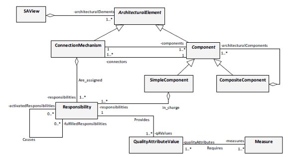
Therefore, the required               concepts are captured from the general and common language used to               design architectures and to validate them according to the quality               attributes values. These concepts and their relationships are               represented in a conceptual model to evaluate the software               architecture at runtime (<i>SAEM</i>).               This model (<a href="#f1">Fig. 1</a>) captures information about the architectural               design, metrics that can be used to analyze indicators of the               quality of the system, and functional aspects that include the               behavior of the system. </span></font> </p>            <p align="justify"><font size="2" face="Verdana"><span lang="en-US">Concepts taken from the               dynamic view (<i>SAView</i> concept in <a href="#f1">Fig. 1</a>) of the software architecture and               their relationships are the fundamental structures. The <i>ArchitecturalElement</i> concept is an abstract entity, which               represents structures that have runtime presence, and they are               included in the dynamic view of the system. Two important concepts               are specialized from it, <i>Component</i> and <i>ConnectionMechanism</i>, which together with the <i>Responsibility</i> concept conform the main structure. They represent               essential elements to build software architectures, describing the               system behavior too.</span></font></p>            <p align="justify"><font size="2" face="Verdana"><span lang="en-US">The <i>Component</i>               concept is an abstract entity, which is a generalization of two               types of components, where one represents simple structures (<i>SimpleComponent</i> concept in <a href="#f1">Fig. 1</a>) and the other               complex structures (<i>CompositeComponent</i> concept in <a href="#f1">Fig. 1</a>) respectively. The <i>SimpleComponent</i> corresponds to a software entity that               could have some runtime presence such as a process, an object,               etc., and it is in charge of a set of responsibilities. A more               complex structure is the <i>CompositeComponent</i>, which depends on a set of components               for carrying out the assigned responsibilities. It can be composed               by both simple components and composite components, delegating the               responsibilities to them, because responsibilities are only               assigned to <i>SimpleComponent</i>.</span></font></p>            <p align="justify"><font size="2" face="Verdana"><span lang="en-US">A <i>Responsibility</i> is a statement about software objects.               It could be an action that an object performs, knowledge that an               object maintains, or a major decision that an object makes that               affect others <a href="#c10">[10]</a>. The relationship between responsibilities is               the kind of cause-effect (<i>Causes</i> relationship in <a href="#f1">Fig. 1</a>), where the               fulfillment of the one or more responsibilities implicates the               execution of others, which are activated to be performed. </span></font>     </p>            <p align="justify"><font size="2" face="Verdana"><span lang="en-US">The forms of interaction               between software elements, such as simple components, are the               connection mechanisms, which are captured in the <i>ConnectionMechanism</i> concept. If connection mechanisms are               complex connectors, they can have assigned responsibilities too.</span></font></p>            <p align="justify"><font size="2" face="Verdana"><span lang="en-US">Finally, for a quantitative               evaluation of quality               attributes, other concepts such as quality attribute values and               measures (metrics) are associated with the responsibilities, since               they are the smallest units at runtime. The <i>QualityAttributeValue</i> concept depends on the measures that are applied to               evaluate quality scenarios. The <i>Measure</i>               concept maintains information about the needed values for the               calculation of a quality indicator.</span></font></p>            ]]></body>
<body><![CDATA[<p align="justify" lang="en-US"><font face="Verdana" size="2">    <br>       </font>       </p>            <p style="margin-top: 0.21cm;" align="center" lang="en-US">       <font face="Verdana" size="2">       <a name="f1"><img src="/img/revistas/cleiej/v14n3/3a04f1.jpg" name="gr&Atilde;&iexcl;ficos1" align="bottom" border="0" height="347" width="618"></a></font></p>            <p style="margin-top: 0.21cm;" align="center"><font size="2" face="Verdana"><span lang="en-US"><b>Figure 1: </b>Conceptual Model for the Evaluation of               Software Architectures (<i>SAEM</i>)</span></font></p>            <p align="justify" lang="en-US"><font face="Verdana" size="2">    <br>       </font>       </p>            <p style="margin-bottom: 0.21cm; text-align: left;" lang="en-US">       <font size="2" face="Verdana"><b>3 An Overview of             Discrete Event Modeling and Simulation</b></font></p>            <p align="justify"><font size="2" face="Verdana"><span lang="en-US">DEVS is a formalism for simulating discrete               event system. It defines system behavior (input/output events and               states, with the respective functions) and the system structure. </span></font>     </p>            <p align="justify"><font size="3" face="Verdana"><font size="2"><span lang="en-US">Zeigler in <a href="#r9">[</a></span><a href="#r9"></a></font><a href="#c9"><font size="2"><span lang="en-US">9]</span></font></a><font size="2"> has proposed a conceptual framework               for modeling and simulation with the purpose of providing a               support to the DEVS formalism. The framework underlying this               formalism has three basic entities (<a href="#f2">Fig. 2</a>):</font></font></p>        <ul>             <li>                       ]]></body>
<body><![CDATA[<p style="margin-bottom: 0.21cm;" align="justify">     <font size="2" face="Verdana"><span lang="en-US"><i>Model</i>: is the system specification,                   defining the structure and behavior needed to generate data                   comparable to data from the real world. Generally, a                   simulation model is a set of instructions, rules, equations,                   constraints, for generating input/output behavior.</span></font></p>         </li>             <li>                       <p style="margin-bottom: 0.21cm;" align="justify">     <font size="2" face="Verdana"><span lang="en-US"><i>Simulator</i>: is a kind of agent (any                   computation system) that executes the instruction of the                   model, generating the behavior. </span></font>         </p>         </li>             <li>                       <p style="margin-bottom: 0.21cm;" align="justify">     <font size="2" face="Verdana"><span lang="en-US"><i>Experimental                     Frame</i>:                   is the specification of the conditions under which the system                   is observed, allowing the experimentation and validation of                   the model.</span></font></p>         </li>            </ul>            <p align="justify"><font size="2" face="Verdana"><span lang="en-US">These entities are linked               by two relationships. The               first, <i>Modeling                 relationship</i>,               links real system and model, it is used to represent the system               (problem) and to validate the model with the real world. The other               relationship, <i>Simulation                 relationship</i>,               links model and simulator, it is employed to assure the simulator               correctness; it guarantees that the simulator generates the output               trajectory given an initial state and an input trajectory.</span></font></p>            <p align="justify"><font size="2" face="Verdana"><span lang="en-US">Keeping separate theses               three entities gives some benefits such as the fact of that the               same model can be executed by different simulators, or that               several experiments can be interchanged to study different               situations. This flexibility has the cost of complexity, but in               many cases is a future investment.</span></font></p>            <p align="justify"><font size="2" face="Verdana"><span lang="en-US">As shown in <a href="#f2">Fig. 2</a>, this               contribution is focused on the model entity of the simulation               approach. The simulation model for the evaluation of quality               attributes is based on the specification of simple primitive DEVS               models (atomic DEVS) and with them complex DEVS models (coupled               DEVS). This means that complex DEVS models are constructed of               simpler ones. In this way, how models are connected is defined,               building a hierarchy of DEVS for the simulation model. DEVS models               employed in this work are specified in the following subsections.</span></font></p>            <p align="justify" lang="en-US"><font face="Verdana" size="2">    ]]></body>
<body><![CDATA[<br>       </font>       </p>            <p style="text-indent: 0.64cm;" align="justify" lang="en-US">       <font face="Verdana" size="2">           <br>         </font>       </p>            <p style="margin-top: 0.21cm;" align="center" lang="en-US">       <font face="Verdana" size="2">       <a name="f2"><img src="/img/revistas/cleiej/v14n3/3a04f2.gif" name="gr&Atilde;&iexcl;ficos2" align="bottom" border="0" height="208" width="426"></a></font></p>            <p style="margin-top: 0.21cm;" align="center"><font size="2" face="Verdana"><span lang="en-US"><b>Figure 2: </b>M&amp;S Framework. Simulation model for               the analysis of quality attributes, based on <a href="#c9">[9]</a></span></font></p>            <p style="text-indent: 0.64cm;" align="justify" lang="en-US">       <font face="Verdana" size="2">           <br>         </font>       </p>            <p style="text-indent: 0.64cm;" align="justify" lang="en-US">       <font face="Verdana" size="2">           <br>         </font>       </p>            <p style="margin-bottom: 0.21cm; text-align: left;"><font size="2">3.1</font><font size="2" face="Verdana"><span lang="en-US"> Atomic DEVS Model with Ports</span></font></p>            ]]></body>
<body><![CDATA[<p align="justify"><font size="2" face="Verdana"><span lang="en-US">This model allows multiple               ports to receive values at the same time <a href="#c9">[9]</a>. The specification is as follows:</span></font></p>            <p style="text-indent: 0.64cm;" align="justify" lang="en-US">       <font face="Verdana" size="2">           <br>         </font>       </p>            <p align="center" lang="en-US"><font face="Verdana" size="2"><img src="/img/revistas/cleiej/v14n3/3a04z1.gif" name="Objeto1" align="bottom" height="16" width="163"></font></p>            <p style="text-indent: 0.64cm;" align="justify" lang="en-US">       <font face="Verdana" size="2">           <br>         </font>       </p>            <p align="justify"><font size="3" face="Verdana"><font size="2"><span lang="en-US">S<img src="/img/revistas/cleiej/v14n3/3a04z2.gif" name="Objeto2" align="left" height="21" hspace="12" width="144">et of               inputs. It is a               set of pairs consisting of an input port and a value. <i>InPorts</i> is the set of possible input ports and <i>X</i></span></font><sub><font size="2"><span lang="en-US"><i>p</i></span></font></sub><font size="2"><span lang="en-US">               is the set of possible values for <i>p</i>               input port.</span></font></font></p>            <p align="justify"><font size="3" face="Verdana"><font size="2"><span lang="en-US">S<img src="/img/revistas/cleiej/v14n3/3a04z3.gif" name="Objeto3" align="left" height="19" hspace="12" width="144">et of               outputs. It is a               set of pairs consisting of an output port and a value. <i>OutPorts</i> is the set of possible output ports and <i>Y</i></span></font><sub><font size="2"><span lang="en-US"><i>p</i></span></font></sub><font size="2"><span lang="en-US">               is the set of possible values for <i>p</i>               output port</span></font></font></p>            <p align="justify"><font size="2" face="Verdana"><span lang="en-US"><i>S </i>Set of sequential states</span></font></p>            <p align="justify"><font size="2" face="Verdana"><span lang="en-US">E<img src="/img/revistas/cleiej/v14n3/3a04z4.gif" name="Objeto4" align="left" height="19" hspace="12" width="63">xternal state               transition function,               where <img src="/img/revistas/cleiej/v14n3/3a04z5.gif" name="Objeto5" align="middle" height="17" width="163">is the set of total states and <i>e</i> is the elapsed time in the state <i>s</i></span></font></p>            ]]></body>
<body><![CDATA[<p align="justify"><font size="2" face="Verdana"><img src="/img/revistas/cleiej/v14n3/3a04z6.gif" name="Objeto6" align="middle" height="19" width="52"> <span lang="en-US">Internal               state transition function</span></font></p>            <p align="justify"><font size="2" face="Verdana"><img src="/img/revistas/cleiej/v14n3/3a04z7.gif" name="Objeto7" align="middle" height="16" width="50"> <span lang="en-US">Output function</span></font></p>            <p align="justify"><font size="2" face="Verdana"><img src="/img/revistas/cleiej/v14n3/3a04z8.gif" name="Objeto8" align="middle" height="22" width="59"> <span lang="en-US">Time               advance function</span></font></p>            <p align="justify" lang="en-US"><font face="Verdana" size="2">    <br>       </font>       </p>            <p style="margin-bottom: 0.21cm; text-align: left;"><font size="2">3.2 </font> <font size="2" face="Verdana"><span lang="en-US">Coupled             DEVS Model</span></font></p>            <p align="justify"><font size="2" face="Verdana"><span lang="en-US">Coupled DEVS model is built with other DEVS models,               which become components of it. To specify coupled models requires:               external interfaces (input/output ports and values), components               (names/references to the component models and their specification               with DEVS), and coupling relationships (external and internal               couplings). So, it is specified in the following form <a href="#r9">[9]</a>.</span></font></p>            <p align="justify" lang="en-US"><font face="Verdana" size="2">    <br>       </font>       </p>            <p align="center" lang="en-US"><font face="Verdana" size="2"><img src="/img/revistas/cleiej/v14n3/3a04z9.gif" name="Objeto9" align="bottom" height="17" width="259"></font></p>            ]]></body>
<body><![CDATA[<p align="justify" lang="en-US"><font face="Verdana" size="2">    <br>       </font>       </p>            <p align="justify"><font size="3" face="Verdana"><font size="2"><span lang="en-US">S<img src="/img/revistas/cleiej/v14n3/3a04z10.gif" name="Objeto10" align="left" height="21" hspace="12" width="142">et of               inputs. It is a               set of pairs consisting of an input port and a value. <i>IPorts</i> is the set of possible input ports and <i>X</i></span></font><sub><font size="2"><span lang="en-US"><i>p</i></span></font></sub><font size="2"><span lang="en-US">               is the set of possible values for <i>p</i>               input port.</span></font></font></p>            <p align="justify"><font size="3" face="Verdana"><font size="2"><span lang="en-US">S<img src="/img/revistas/cleiej/v14n3/3a04z11.gif" name="Objeto11" align="left" height="21" hspace="12" width="139">et of outputs. It is a               set of pairs consisting of an output port and a value. <i>OPorts</i> is the set of possible output ports and <i>Y</i></span></font><sub><font size="2"><span lang="en-US"><i>p</i></span></font></sub><font size="2"><span lang="en-US"><i>               </i>is the set of               possible values for <i>p</i> output port</span></font></font></p>            <p align="justify"><font size="2" face="Verdana"><img src="/img/revistas/cleiej/v14n3/3a04z12.gif" name="Objeto12" align="bottom" height="12" width="14"> <span lang="en-US">Set               of component names</span></font></p>            <p align="justify"><font size="3" face="Verdana"><font size="2"><span lang="en-US"><i>M</i></span></font><sub><font size="2"><span lang="en-US"><i>d</i></span></font></sub><font size="2"><span lang="en-US"> Component models, for each <i>d</i>:               <img src="/img/revistas/cleiej/v14n3/3a04z13.gif" name="Objeto13" align="middle" height="18" width="150"> </span></font></font> </p>            <p align="justify"><font size="2" face="Verdana"><img src="/img/revistas/cleiej/v14n3/3a04z14.gif" name="Objeto14" align="bottom" height="18" width="303"> <span lang="en-US">External               Input Coupling</span></font></p>            <p align="justify"><font size="2" face="Verdana"><img src="/img/revistas/cleiej/v14n3/3a04z15.gif" name="Objeto15" align="bottom" height="18" width="303"> <span lang="en-US">External               Output Coupling</span></font></p>            <p align="justify"><font size="2" face="Verdana"><img src="/img/revistas/cleiej/v14n3/3a04z16.gif" name="Objeto16" align="bottom" height="17" width="303"> <span lang="en-US">Internal Coupling</span></font></p>            <p align="justify"><font size="2" face="Verdana"><span lang="en-US"><i>Select</i>: tie-breaking function (used in classic               DEVS but eliminated in parallel DEVS)</span></font></p>            ]]></body>
<body><![CDATA[<p align="justify" lang="en-US"><font face="Verdana" size="2">    <br>       </font>       </p>            <p style="margin-bottom: 0.21cm; text-align: left;"><font size="2">4 </font> <font size="2" face="Verdana"><span lang="en-US"><b>Discrete Event               Simulation Model for the Analysis of Quality Attributes</b></span></font></p>            <p align="justify"><font size="2" face="Verdana"><span lang="en-US">This work is focused on the               specification of elements that represent basic structures of the               software architecture domain in the discrete event simulation               model. The               relationships between the software architecture concepts and the               simulation elements are defined to translate the conceptual model               to evaluate software architecture (<a href="#f1">Fig. 1</a>) into a hierarchical               simulation model (<a href="#t1">Table 1</a>).</span></font></p>            <p align="justify"><font size="2" face="Verdana"><span lang="en-US">The simulation model is               built considering the guidelines suggested by Zeigler <a href="#c9">[9]</a> and other authors <a href="#c15">[15]</a><a name="c15."></a>. The               specification is composed of DEVS models, which are structured in               a modular and hierarchical way. The elements or building blocks               are defined following some characteristics that each block               (element of the simulation model) has to fulfill <a href="#c15">[15]</a>: </span></font>     </p>        <ul>             <li>                       <p style="margin-bottom: 0.21cm;" align="justify">     <font size="2" face="Verdana"><span lang="en-GB"><i>Self-contained</i>: refers to the use of local                   information and local processes.</span></font></p>         </li>             <li>                       <p style="margin-bottom: 0.21cm;" align="justify">     <font size="2" face="Verdana"><span lang="en-GB"><i>Interoperable</i></span><span lang="en-US">: determines that a building block                   may cooperate with other building blocks. All the system </span><span lang="en-GB">elements</span><span lang="en-US"> form the system that will be simulated.</span></font></p>         </li>             <li>                       ]]></body>
<body><![CDATA[<p style="margin-bottom: 0.21cm;" align="justify">     <font size="2" face="Verdana"><span lang="en-GB"><i>Reusable</i></span><span lang="en-US">: means that the simulation building                   blocks could be instantiated more than once in the same model                   or in different simulation models for several studies. </span></font>         </p>         </li>             <li>                       <p style="margin-bottom: 0.21cm;" align="justify">     <font size="2" face="Verdana"><span lang="en-GB"><i>Replaceable</i></span><span lang="en-US">: indicates that a building block in                   a simulation model may be removed from it and another building                   block may take its place.</span></font></p>         </li>             <li>                       <p style="margin-bottom: 0.21cm;" align="justify">     <font size="2" face="Verdana"><span lang="en-GB"><i>Encapsulated</i></span><span lang="en-US">: keeps secret mechanism inside,                   encapsulating the internal structure of a building block in                   the simulation model. The purpose is to hide the complexity of                   the mechanism from the user.</span></font></p>         </li>            </ul>            <p style="margin-top: 0.78cm; margin-bottom: 0.18cm; line-height: 0.39cm; page-break-after: avoid;" align="center" lang="en-US">  <font size="2" style="font-size: 10pt" face="Verdana"><b>Table 1:</b>             Correspondence between conceptual elements (software architecture)             and simulation elements (DEVS)
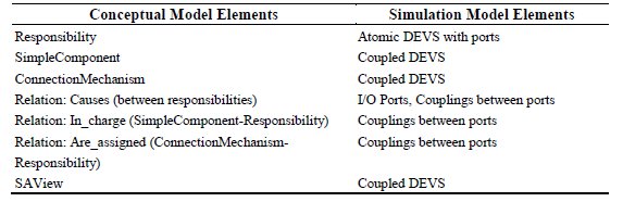
</font></p>            <center>     <font face="Verdana" size="2">     <img src="/img/revistas/cleiej/v14n3/3a04t1.jpg" name="t1" align="bottom" border="0">     </font> </center>            <p align="justify" lang="en-US"><font face="Verdana" size="2">    <br>       </font>       </p>            ]]></body>
<body><![CDATA[<p align="justify"><font size="2" face="Verdana"><span lang="en-US">Therefore, the main               concepts of the architectural model, represented by the conceptual               model in <a href="#f1">Fig. 1</a>, are transformed into elements of the simulation               model. Consequently, a hierarchy of DEVS models is obtained. An               atomic DEVS model is defined for the <i>Responsibility</i> concept (<a href="#t1">Table 1</a>), and three coupled models are               specified, one for the <i>SimpleComponent</i> concept, other for the <i>ConnectionMechanism</i> concept and another one for the <i>SAView</i> concept (<a href="#t1">Table 1</a>).</span></font></p>            <p align="justify" lang="en-US"><font face="Verdana" size="2">    <br>       </font>       </p>            <p style="margin-bottom: 0.21cm; text-align: left;"><font size="2">4.1 </font> <font size="2" face="Verdana"><span lang="en-US">DEVS             Model for Responsibility Concept (<i>RM</i>)</span></font></p>            <p align="justify"><font size="2" face="Verdana"><span lang="en-US">The <i>Responsibility</i> concept is the smallest (primitive) unit of the               dynamic elements in the proposed architectural model.               Responsibilities are linked among them by a cause-effect               relationship (<i>Causes</i>).               The <i>fulfilled</i> <i>responsibilities</i> active other responsibilities (<i>activated</i> <i>responsibilities</i>).</span></font></p>            <p align="justify"><font size="2" face="Verdana"><span lang="en-US">This element (<a href="#f3">Fig. 3</a> (a)),               from an architectural model, is translated into an atomic DEVS               with ports, in the simulation model, called <i>Responsibility Model</i> (<i>RM</i>) (<a href="#f3">Fig. 3</a>(b)). Specifying a DEVS with               ports provides adaptability to the model, allowing an easier model               evolution. Thus, when some other aspects need to be considered,               inputs ports could be easily introduced. In the same way, when               extra information from <i>RM</i> is required to be analyzed, output               ports could be added easily. These changes do not impact in the               whole DEVS for the <i>Responsibility</i> concept.</span></font></p>            <p align="justify"><font size="2" face="Verdana"><span lang="en-US">Each <i>RM</i>               calculates its output values, related to its own states or to the               measurement of quality attributes. Currently, the parameters               included in the simulation elements would allow measuring               performance aspects. Each element calculates the execution time to               compute the turnaround time of the system when a stimulus arrives. </span></font> </p>            <p align="justify"><font size="2" face="Verdana"><span lang="en-US">The relationships between               responsibilities (<i>RM</i>) in the simulation model are given by               the input/output ports, with their respective constraints to keep               the cause-effect relationships.</span></font></p>             <p align="justify" lang="en-US"><font face="Verdana" size="2"><a name="f3"><img src="/img/revistas/cleiej/v14n3/3a04f3.gif"></a><span id="Marco1" style="border: medium none ; padding: 0cm; background: rgb(255, 255, 255) none repeat scroll 0% 50%; -moz-background-clip: initial; -moz-background-origin: initial; -moz-background-inline-policy: initial; float: left; width: 0.48cm; height: 0.53cm;" dir="ltr">       </span></font></p>                <p style="margin-top: 0.21cm;" align="center"><font size="2" face="Verdana"><span lang="en-US"><b>Figure 3: </b>(a) <i>Responsibility</i> concept and the causal relationship,               from architectural model. (b) <i>RM</i>               (atomic DEVS with ports) with the transition diagram inside for               representing the dynamic</span></font></p>            ]]></body>
<body><![CDATA[<p align="justify" lang="en-US"><font face="Verdana" size="2">    <br>       </font>       </p>            <p align="justify"><font size="2" face="Verdana"><span lang="en-US">To sum up, formally, the <i>Responsibility</i> concept is specified (DEVS) defining the set of               inputs, outputs and states, the external and internal transition               functions, the output function and the time advance function.</span></font></p>            <p style="text-indent: 0.64cm;" align="justify" lang="en-US">       <font face="Verdana" size="2">           <br>         </font>       </p>            <p align="center" lang="en-US"><font face="Verdana" size="2"><img src="/img/revistas/cleiej/v14n3/3a04z17.gif" name="Objeto17" align="bottom" height="19" width="242"></font></p>            <p align="justify" lang="en-US"><font face="Verdana" size="2">    <br>       </font>       </p>            <p style="text-align: left;"><font size="2">4.1.1</font><font size="2" face="Verdana"><span lang="en-US"><i><span style="text-decoration: none;">Set                 of Inputs                 (X</span></i></span></font><sub><font size="2" face="Verdana"><span lang="en-US"><i><span style="text-decoration: none;">RM</span></i></span></font></sub><font size="2" face="Verdana"><span lang="en-US"><i><span style="text-decoration: none;">)</span></i></span></font></p>            <p align="justify"><font size="2" face="Verdana"><span lang="en-US">The set of input values represents information about the               fulfilled responsibilities and indicates the level in which each               predecessor responsibility is completed. The only needed               information for activating a responsibility initially is to know               if previous responsibilities have finished their executions. </span></font>     </p>            ]]></body>
<body><![CDATA[<p align="justify"><font size="2" face="Verdana"><span lang="en-US">This set of inputs could be               increased by incorporating more details to the model, with the               purpose of evaluating other quality aspects of the system. In               consequence, maintaining a model with ports allows that these               changes can be easily added. </span></font> </p>            <p style="text-indent: 0.64cm;" align="justify" lang="en-US">       <font face="Verdana" size="2">           <br>         </font>       </p>            <p align="center"><font face="Verdana" size="2"><img src="/img/revistas/cleiej/v14n3/3a04z18.gif" name="Objeto18" align="middle" height="18" width="129"> </font> </p>            <p align="justify"><font size="2" face="Verdana"><span lang="en-US">where<img src="/img/revistas/cleiej/v14n3/3a04z19.gif" name="Objeto19" align="middle" height="19" width="156"></span></font></p>            <p style="text-indent: 0.64cm;" align="justify" lang="en-US">       <font face="Verdana" size="2">           <br>         </font>       </p>            <p align="justify"><font size="2" face="Verdana"><span lang="en-US"><i>Set of input ports: </i></span></font>     </p>            <p align="justify"><font size="2" face="Verdana"><img src="/img/revistas/cleiej/v14n3/3a04z20.gif" name="Objeto20" align="middle" height="17" width="64"> <span lang="en-US">where <i>prip</i> is the input port (<i>activatedResponsibilities</i>, <a href="#f3">Fig. 3</a>(a)) that is connected to the output ports of               other responsibilities (<i>fullfilledResponsibilities</i>, <a href="#f3">Fig. 3</a>(a)).</span></font></p>            <p align="justify"><font size="2" face="Verdana"><span lang="en-US"><i>Set of input values for prip: </i></span></font>     </p>            ]]></body>
<body><![CDATA[<p align="justify" lang="en-US"><font face="Verdana" size="2"><img src="/img/revistas/cleiej/v14n3/3a04z21.gif" name="Objeto21" align="bottom" height="18" width="99"></font></p>            <p align="justify" lang="en-US"><font size="2" face="Verdana">This set might incorporate other values when other aspects           need to be considered.</font></p>            <p align="justify" lang="en-US"><font face="Verdana" size="2">    <br>       </font>       </p>            <p style="text-align: left;"><font size="2">4.1.2 </font> <font size="2" face="Verdana"><span lang="en-US"><i><span style="text-decoration: none;">The                 Set of States                 (S</span></i></span></font><sub><font size="2" face="Verdana"><span lang="en-US"><i><span style="text-decoration: none;">RM</span></i></span></font></sub><font size="2" face="Verdana"><span lang="en-US"><i><span style="text-decoration: none;">)</span></i></span></font></p>            <p align="justify"><font size="2" face="Verdana"><span lang="en-US">A responsibility reflects               a point where the system makes a change in its state, because it               is interrogated or affected by other architectural element. So the               states allow the designer to analyze if the system is active (<i>active</i>), in execution (<i>executing</i>) or passive (<i>inactive</i>)               mode in this point.</span></font></p>            <p align="justify"><font size="2" face="Verdana"><span lang="en-US">For this model, a state is               given by a phase and a sigma value. So, the set of states is               defined as follows.</span></font></p>            <p style="text-indent: 0.64cm;" align="justify" lang="en-US">       <font face="Verdana" size="2">           <br>         </font>       </p>            <p align="center"><font size="3" face="Verdana"><font size="2"><span lang="en-US"><i>S</i></span></font><sub><font size="2"><span lang="en-US"><i>RM</i></span></font></sub><font size="2"><span lang="en-US">= {<i>inactive</i>, <i>active</i>, <i>executing</i>} x <img src="/img/revistas/cleiej/v14n3/3a04z22.gif" name="Objeto22" align="middle" height="25" width="24"></span></font></font></p>            ]]></body>
<body><![CDATA[<p style="text-indent: 0.64cm;" align="justify" lang="en-US">       <font face="Verdana" size="2">           <br>         </font>       </p>            <p align="justify"><font size="2" face="Verdana"><span lang="en-US">where the possible phases are (<a href="#f3">Fig. 3</a> (b)): </span></font>     </p>        <ul>             <li>                       <p style="margin-bottom: 0.21cm;" align="justify">     <font size="2" face="Verdana"><span lang="en-US"><i>inactive</i>: passive </span><span lang="en-GB">state</span><span lang="en-US">,                   waiting for an external event. The system stays in this phase                   until an event occurs and interrupts the system condition.</span></font></p>         </li>             <li>                       <p style="margin-bottom: 0.21cm;" align="justify">     <font size="2" face="Verdana"><span lang="en-US"><i>active</i>: transitory state. This phase                   starts an internal transition that generates a needed output                   for the system evaluation. </span><span lang="en-GB">This</span><span lang="en-US">                   stage indicates the execution of a responsibility has been                   started. The duration of this phase is null and it cannot be                   interrupted by external events.</span></font></p>         </li>             <li>                       <p style="margin-bottom: 0.21cm;" align="justify">     <font size="2" face="Verdana"><span lang="en-US"><i>executing</i>: this stage </span><span lang="en-GB">indicates</span><span lang="en-US">                   that the responsibility is being performed, where execution                   means the processing of code in software domain.</span></font></p>         </li>            </ul>            ]]></body>
<body><![CDATA[<p style="text-indent: 0.64cm;" align="justify"><font size="2" face="Verdana"><span lang="en-US">&Iuml;&fnof;: resting time in the               state.</span></font></p>            <p align="justify"><font size="2" face="Verdana"><span lang="en-US">The quantitative aspects,               represented in the conceptual model and related to the quality               attributes, are modeled as fixed parameters of the atomic model or               as calculated metrics in the simulation. They are measured during               the execution.               Thus, adding parameters to <i>RM</i> will allow the evaluation of quality               attributes in different scenarios based on the execution of the               system.</span></font></p>            <p align="justify"><font size="2" face="Verdana"><span lang="en-US">At present, the model only includes one parameter               that provides information for analyzing dynamics aspects:</span></font></p>        <ul>             <li>                       <p style="margin-bottom: 0.21cm;" align="justify">     <font size="2" face="Verdana"><span lang="en-US"><i>execution_time</i>, fix parameter of the model,                   indicates the time that an architectural element needs to                   carry out a responsibility; </span><span lang="en-GB">this</span><span lang="en-US">                   means time that a responsibility uses to be performed. It sums                   up the metrics associated to the <i>Measure</i> concept in the conceptual model (<a href="#f1">Fig. 1</a>).</span></font></p>         </li>            </ul>            <p align="justify" lang="en-US"><font face="Verdana" size="2">    <br>       </font>       </p>            <p style="text-align: left;"><font size="2">4.1.3 </font> <font size="2" face="Verdana"><span lang="en-US"><i><span style="text-decoration: none;">Set                 of Outputs (Y</span></i></span></font><sub><font size="2" face="Verdana"><span lang="en-US"><i><span style="text-decoration: none;">RM</span></i></span></font></sub><font size="2" face="Verdana"><span lang="en-US"><i><span style="text-decoration: none;">)</span></i></span></font></p>            <p align="justify"><font size="2" face="Verdana"><span lang="en-US">A responsibility is in               charge of emitting two types of output values. One related to its state, data of               interest for the successor responsibilities (activated               responsibilities as consequence of the execution of others), and               other related to the values used for measuring aspects about               quality attributes.</span></font></p>            ]]></body>
<body><![CDATA[<p align="justify" lang="en-US"><font face="Verdana" size="2">    <br>       </font>       </p>            <p align="center"><font face="Verdana" size="2"><img src="/img/revistas/cleiej/v14n3/3a04z23.gif" name="Objeto23" align="middle" height="18" width="261"> </font> </p>            <p align="justify"><font size="3" face="Verdana"> <font style="font-size: 10pt;" size="2"><span lang="en-US">where</span></font><font size="2"><span lang="en-US"> </span></font></font> <font size="2" face="Verdana"><span lang="en-US"> <img src="/img/revistas/cleiej/v14n3/3a04z24.gif" name="Objeto24" align="middle" height="18" width="169"></span></font><font size="2" face="Verdana"><span lang="en-US"> </span></font>     </p>            <p align="justify" lang="en-US"><font face="Verdana" size="2">    <br>       </font>       </p>            <p align="justify" lang="en-US"><font size="2" face="Verdana"><i>Set of output ports:</i></font></p>            <p align="justify"><font size="2" face="Verdana"><img src="/img/revistas/cleiej/v14n3/3a04z25.gif" name="Objeto25" align="middle" height="17" width="99"> <span lang="en-US">where <i>srop</i> is the output port for the events generated with the               purpose of notifying other responsibilities and <i>mop </i>is the measure output port for evaluating quality               attributes (in this work only was considered a performance               indicator).</span></font></p>            <p align="justify" lang="en-US"><font size="2" face="Verdana"><i>Set of values for srop:</i></font></p>            <p align="justify" lang="en-US"><font face="Verdana" size="2"><img src="/img/revistas/cleiej/v14n3/3a04z26.gif" name="Objeto26" align="bottom" height="18" width="150"></font></p>            ]]></body>
<body><![CDATA[<p align="justify"><font size="2" face="Verdana"><span lang="en-US">The possible values are:</span></font></p>        <ul>             <li>                       <p style="margin-bottom: 0.21cm;" align="justify">     <font size="2" face="Verdana"><span lang="en-US"><i>activated</i>: this value is emitted when the                   execution of the responsibility has been started. The                   responsibility is ready for the execution.</span></font></p>         </li>             <li>                       <p style="margin-bottom: 0.21cm;" align="justify">     <font size="2" face="Verdana"><span lang="en-US"><i>finished</i>: this value is generated when the                   responsibility has been carried out, after its execution has                   been finished. </span></font> </p>         </li>            </ul>            <p align="justify" lang="en-US"><font size="2" face="Verdana"><i>Set of values for mop:</i></font></p>            <p style="margin-left: 0.5cm; text-indent: -0.5cm;" align="justify">       <font size="2" face="Verdana"><span lang="en-US">The set               of values for this port indicates the needed execution time to perform the responsibility.</span></font></p>            <p align="justify" lang="en-US"><font face="Verdana" size="2"><img src="/img/revistas/cleiej/v14n3/3a04z27.gif" name="Objeto27" align="bottom" height="20" width="59"></font></p>            <p align="justify" lang="en-US"><font face="Verdana" size="2">    ]]></body>
<body><![CDATA[<br>       </font>       </p>            <p style="text-align: left;"><font size="2">4.1.4 </font> <font size="2" face="Verdana"><span lang="en-US"><i><span style="text-decoration: none;">Internal Transition                 Function                 (&iuml;&#65533;&curren;</span></i></span></font><sub><font size="2" face="Verdana"><span lang="en-US"><i><span style="text-decoration: none;">RM,int</span></i></span></font></sub><font size="2" face="Verdana"><span lang="en-US"><i><span style="text-decoration: none;">)</span></i></span></font></p>            <p align="justify"><font size="2" face="Verdana"><span lang="en-US">The internal transition               function (Fig. 3               (b)) defines the next state for the responsibility, as result of               the elapsed time without an external event has taken place.</span></font></p>            <p align="justify"><font size="2" face="Verdana"><span lang="en-US">The <i>active</i>               transitory state indicates that the responsibility can be carried               out, because their predecessors (fulfilled responsibilities) have               been finished in a suitable form. It communicates its activated               state to the corresponding simulation elements; it has been               started. So that, an internal transition is required that allows               emitting an event using the correct port and changes automatically               its state to <i>executing</i>.</span></font></p>            <p align="justify" lang="en-US"><font face="Verdana" size="2"><img src="/img/revistas/cleiej/v14n3/3a04z28.gif" name="Objeto28" align="bottom" height="18" width="219"></font></p>            <p align="justify"><font size="2" face="Verdana"><span lang="en-US">The other internal               transition happens when the execution time has been elapsed,               returning to the passive state (<i>inactive</i>), in               standby, waiting for other external event.</span></font></p>            <p align="justify" lang="en-US"><font face="Verdana" size="2"><img src="/img/revistas/cleiej/v14n3/3a04z29.gif" name="Objeto29" align="bottom" height="18" width="172"></font></p>            <p align="justify" lang="en-US"><font face="Verdana" size="2">    <br>       </font>       </p>            <p style="text-align: left;"><font size="2">4.1.5 </font> <font size="2" face="Verdana"><span lang="en-US"><i><span style="text-decoration: none;">External Transition                 Function                 (&iuml;&#65533;&curren;</span></i></span></font><sub><font size="2" face="Verdana"><span lang="en-US"><i><span style="text-decoration: none;">RM,ext</span></i></span></font></sub><font size="2" face="Verdana"><span lang="en-US"><i><span style="text-decoration: none;">)</span></i></span></font></p>            ]]></body>
<body><![CDATA[<p align="justify"><font size="2" face="Verdana"><span lang="en-US">This function makes a state               transition when an external event               has happened (<a href="#f3">Fig. 3</a> (b)). In other words, this change occurs when <i>finished</i> value is received from the fulfilled               responsibilities. Therefore, <i>x</i> is equals to <i>finished</i>.</span></font></p>            <p style="margin-bottom: 0.21cm;" align="justify"><font size="2" face="Verdana"><span lang="en-US">i<img src="/img/revistas/cleiej/v14n3/3a04z30.gif" name="Objeto30" align="left" height="35" hspace="12" width="176">f               phase=<i>inactive</i></span></font></p>            <p align="justify"><font size="2" face="Verdana"><span lang="en-US">if phase= <i>active</i> or <i>executing</i></span></font></p>            <p align="justify" lang="en-US"><font face="Verdana" size="2">    <br>       </font>       </p>            <p style="text-align: left;"><font size="2">4.1.6 </font> <font size="2" face="Verdana"><span lang="en-US"><i><span style="text-decoration: none;">Output                 Function                 (&Icirc;&raquo;</span></i></span></font><sub><font size="2" face="Verdana"><span lang="en-US"><i><span style="text-decoration: none;">RM</span></i></span></font></sub><font size="2" face="Verdana"><span lang="en-US"><i><span style="text-decoration: none;">)</span></i></span></font></p>            <p align="justify"><font size="2" face="Verdana"><span lang="en-US">The output function               generates output values and then makes the internal transition of states (<a href="#f3">Fig. 3</a> (b)).</span></font></p>            <p align="justify" lang="en-US"><font face="Verdana" size="2"><img src="/img/revistas/cleiej/v14n3/3a04z31.gif" name="Objeto31" align="bottom" height="17" width="175"></font></p>            <p align="justify"><font size="2" face="Verdana"><img src="/img/revistas/cleiej/v14n3/3a04z32.gif" name="Objeto32" align="middle" height="18" width="239"> <span lang="en-US">where <i>m</i> corresponds to the execution time.</span></font></p>            <p align="justify" lang="en-US"><font face="Verdana" size="2">    ]]></body>
<body><![CDATA[<br>       </font>       </p>            <p style="text-align: left;"><font size="2">4.1.7 </font> <font size="2" face="Verdana"><span lang="en-US"><i><span style="text-decoration: none;">Time Advance Function                 (ta</span></i></span></font><sub><font size="2" face="Verdana"><span lang="en-US"><i><span style="text-decoration: none;">RM</span></i></span></font></sub><font size="2" face="Verdana"><span lang="en-US"><i><span style="text-decoration: none;">)</span></i></span></font></p>            <p align="justify"><font size="2" face="Verdana"><span lang="en-US">This function defines the               time that the responsibility has been in a state. For the proposed model: <img src="/img/revistas/cleiej/v14n3/3a04z33.gif" name="Objeto33" align="middle" height="18" width="63"></span></font></p>            <p align="justify"><font size="2" face="Verdana"><img src="/img/revistas/cleiej/v14n3/3a04z34.gif" name="Objeto34" align="middle" height="17" width="94"><span lang="en-US">where <i>s=(active, &Iuml;&fnof;)</i> is a transitory state.</span></font></p>            <p align="justify"><font size="2" face="Verdana"><img src="/img/revistas/cleiej/v14n3/3a04z35.gif" name="Objeto35" align="middle" height="17" width="183"> <span lang="en-US">where               the <i>execution_time</i> is the specified parameter for this               model initially.</span></font></p>            <p align="justify"><font size="2" face="Verdana"><img src="/img/revistas/cleiej/v14n3/3a04z36.gif" name="Objeto36" align="middle" height="17" width="108"><span lang="en-US">where <i>s =(inactive, &Iuml;&fnof;)</i> is a passive state.</span></font></p>            <p align="justify" lang="en-US"><font face="Verdana" size="2">    <br>       </font>       </p>            <p style="margin-bottom: 0.21cm;" align="justify"><font size="2">4.2 </font> <font size="2" face="Verdana"><span lang="en-US">DEVS Model for             the Simple Component (<i>SC</i>) </span></font> </p>            <p align="justify"><font size="2" face="Verdana"><span lang="en-US">The simple component in the               architectural model is in charge of a set of responsibilities (<a href="#f4">Fig. 4</a> (a)). So, this               structure can be mapped to a coupled DEVS model (<a href="#f4">Fig. 4</a> (b)). The               relationship between the simple component and their               responsibilities can be represented as a hierarchy of DEVS models,               structured in a modular way. </span></font> </p>            ]]></body>
<body><![CDATA[<p align="justify" lang="en-US"><font face="Verdana" size="2">    <br>       </font>       </p>            <p style="margin-top: 0.21cm;" align="center" lang="en-US">       <font face="Verdana" size="2">       <a name="f4"><img src="/img/revistas/cleiej/v14n3/3a04f4.gif"><img src="/img/revistas/cleiej/v14n3/3a04f4b.gif" align="left" hspace="12"></a></font></p>            <p style="margin-top: 0.21cm;" align="center"><font size="2" face="Verdana"><span lang="en-US"><b>Figure 4: </b><i>SimpleComponent</i> concept and the relationship with the <i>Responsibility</i> concept. The simple component has a set               of responsibilities in charge (<i>In_charge</i>               relationship)</span></font></p>            <p style="text-indent: 0.64cm;" align="justify" lang="en-US">       <font face="Verdana" size="2">           <br>         </font>       </p>            <p align="justify"><font size="2" face="Verdana"><span lang="en-US"><i>RM</i>, which is specified for the <i>Responsibility</i> concept, could be instantiated as               components of <i>SC</i>. The coupled model for the <i>SimpleComponent</i> concept is specified in the following               form.</span></font></p>            <p style="text-indent: 0.64cm;" align="justify" lang="en-US">       <font face="Verdana" size="2">           <br>         </font>       </p>            <p align="center" lang="en-US"><font face="Verdana" size="2"><img src="/img/revistas/cleiej/v14n3/3a04z37.gif" name="Objeto37" align="bottom" height="20" width="296"></font></p>            ]]></body>
<body><![CDATA[<p style="text-indent: 0.64cm;" align="justify" lang="en-US">       <font face="Verdana" size="2">           <br>         </font>       </p>            <p style="text-align: left;"><font size="2">4.2.1</font><font size="2" face="Verdana"><span lang="en-US"><i><span style="text-decoration: none;">Set                 of Inputs (X</span></i></span></font><sub><font size="2" face="Verdana"><span lang="en-US"><i><span style="text-decoration: none;">SC</span></i></span></font></sub><font size="2" face="Verdana"><span lang="en-US"><i><span style="text-decoration: none;">)</span></i></span></font></p>            <p align="justify"><font size="2" face="Verdana"><span lang="en-US"><i>SC</i> has a set of input ports, where the               input values are propagated to the components of this model. In               this way, the input ports of this DEVS are connected to the input               ports of the corresponding components, instances of <i>RM</i>. To the input ports, values that have been emitted               from the previous components arrive, obtaining information to               activate the suitable modules.</span></font></p>            <p align="justify" lang="en-US"><font face="Verdana" size="2">    <br>       </font>       </p>            <p align="center"><font face="Verdana" size="2"><img src="/img/revistas/cleiej/v14n3/3a04z38.gif" name="Objeto38" align="middle" height="18" width="125"> </font> </p>            <p align="justify"><font size="2" face="Verdana"><span lang="en-US">where<img src="/img/revistas/cleiej/v14n3/3a04z39.gif" name="Objeto39" align="middle" height="16" width="68"></span></font></p>            <p align="justify" lang="en-US"><font face="Verdana" size="2">    <br>       </font>       </p>            ]]></body>
<body><![CDATA[<p align="justify" lang="en-US"><font size="2" face="Verdana"><i>Set of input ports:</i></font></p>            <p align="justify"><font size="2" face="Verdana"><img src="/img/revistas/cleiej/v14n3/3a04z40.gif" name="Objeto40" align="middle" height="18" width="79"> <span lang="en-US">where <i>peip</i> is the input port that receives information about               the previous architectural elements, and it is connected to the               input ports of the corresponding components.</span></font></p>            <p align="justify" lang="en-US"><font size="2" face="Verdana"><i>Set of input values:</i></font></p>            <p align="justify"><font size="2" face="Verdana"><span lang="en-US">The set of input values               represent information about the predecessor elements. This               information is related to the execution end of the previous components, which is needed to               activate the execution of the corresponding components.</span></font></p>            <p align="justify" lang="en-US"><font face="Verdana" size="2"><img src="/img/revistas/cleiej/v14n3/3a04z41.gif" name="Objeto41" align="bottom" height="18" width="106"></font></p>            <p align="justify" lang="en-US"><font face="Verdana" size="2">    <br>       </font>       </p>            <p style="text-align: left;"><font size="2">4.2.2 </font> <font size="2" face="Verdana"><span lang="en-US"><i><span style="text-decoration: none;">Set                 of Outputs (Y</span></i></span></font><sub><font size="2" face="Verdana"><span lang="en-US"><i><span style="text-decoration: none;">SC</span></i></span></font></sub><font size="2" face="Verdana"><span lang="en-US"><i><span style="text-decoration: none;">)</span></i></span></font></p>            <p align="justify" lang="en-US"><font size="2" face="Verdana">The output ports propagate the events generated by the           components of this model to other simulation elements that represent           architectural elements from the conceptual model.</font></p>            <p align="justify" lang="en-US"><font face="Verdana" size="2">    ]]></body>
<body><![CDATA[<br>       </font>       </p>            <p align="center"><font face="Verdana" size="2"><img src="/img/revistas/cleiej/v14n3/3a04z42.gif" name="Objeto42" align="middle" height="18" width="245"> </font> </p>            <p align="justify"><font size="2" face="Verdana"><span lang="en-US">where <img src="/img/revistas/cleiej/v14n3/3a04z43.gif" name="Objeto43" align="middle" height="18" width="212"></span></font></p>            <p align="justify" lang="en-US"><font face="Verdana" size="2">    <br>       </font>       </p>            <p align="justify" lang="en-US"><font size="2" face="Verdana"><i>Set of output ports:</i></font></p>            <p align="justify"><font size="2" face="Verdana"><img src="/img/revistas/cleiej/v14n3/3a04z44.gif" name="Objeto44" align="middle" height="18" width="102"> <span lang="en-US">where <i>seop</i> is the output port that emits events to the               successors elements, and <i>mop</i> is the output port that returns a               measure value, associated to indicators of quality attributes.</span></font></p>            <p align="justify" lang="en-US"><font size="2" face="Verdana"><i>Set of output values for seop:</i></font></p>            <p align="justify" lang="en-US"><font face="Verdana" size="2"><img src="/img/revistas/cleiej/v14n3/3a04z45.gif" name="Objeto45" align="middle" height="18" width="146"></font></p>            <p align="justify"><font size="2" face="Verdana"><span lang="en-US">where:</span></font></p>        <ul>             ]]></body>
<body><![CDATA[<li>                       <p style="margin-bottom: 0.21cm;" align="justify">     <font size="2" face="Verdana"><span lang="en-US"><i>activated</i>: indicates </span><span lang="en-GB">that</span><span lang="en-US">                   the execution of the component has been started. The                   corresponding responsibilities are activated inside of this                   component.</span></font></p>         </li>             <li>                       <p style="margin-bottom: 0.21cm;" align="justify">     <font size="2" face="Verdana"><span lang="en-US"><i>finished</i>: indicates that </span><span lang="en-GB">the</span><span lang="en-US"> execution of the component has been ended. No                   responsibility is active</span>.</font></p>         </li>            </ul>            <p align="justify" lang="en-US"><font size="2" face="Verdana"><i>Set of output values for mop:</i></font></p>            <p align="justify" lang="en-US"><font size="2" face="Verdana">The output values are represented by the set of real numbers.           It indicates a value of a needed measure to calculate a quality index           of the software. </font> </p>            <p align="justify" lang="en-US"><font face="Verdana" size="2"><img src="/img/revistas/cleiej/v14n3/3a04z46.gif" name="Objeto46" align="bottom" height="22" width="61"></font></p>            <p align="justify" lang="en-US"><font face="Verdana" size="2">    <br>       </font>       </p>            ]]></body>
<body><![CDATA[<p style="text-align: left;"><font size="2">4.2.3 </font> <font size="2" face="Verdana"><span lang="en-US"><i><span style="text-decoration: none;">Set                 of Components                 (D</span></i></span></font><sub><font size="2" face="Verdana"><span lang="en-US"><i><span style="text-decoration: none;">SC</span></i></span></font></sub><font size="2" face="Verdana"><span lang="en-US"><i><span style="text-decoration: none;">)</span></i></span></font></p>            <p align="justify"><font size="3" face="Verdana"><font size="2"><span lang="en-US">This set details the               references to the components of the coupled model. In the present               work, <i>D</i></span></font><sub><font size="2"><span lang="en-US"><i>SC</i></span></font></sub><font size="2"><span lang="en-US"> is the set of references to <i>RM</i>               instances that are part of the <i>SC</i>.</span></font></font></p>            <p align="justify" lang="en-US"><font face="Verdana" size="2">    <br>       </font>       </p>            <p style="text-align: left;"><font size="2">4.2.4</font><font size="2" face="Verdana"><span lang="en-US"><i><span style="text-decoration: none;">Component                 Models                 (M</span></i></span></font><sub><font size="2" face="Verdana"><span lang="en-US"><i><span style="text-decoration: none;">SC,d</span></i></span></font></sub><font size="2" face="Verdana"><span lang="en-US"><i><span style="text-decoration: none;">)</span></i></span></font></p>            <p align="justify"><font face="Verdana" size="2"><img src="/img/revistas/cleiej/v14n3/3a04z47.gif" name="Objeto47" align="middle" height="18" width="61"> <img src="/img/revistas/cleiej/v14n3/3a04z48.gif" name="Objeto48" align="middle" height="18" width="47"> </font> </p>            <p align="justify"><font size="2" face="Verdana"><span lang="en-US">where <i>d</i> is the reference name of the <i>RM</i>               model (names of the corresponding responsibility in the               architectural model).</span></font></p>            <p align="justify" lang="en-US"><font face="Verdana" size="2">    <br>       </font>       </p>            <p style="text-align: left;"><font size="2" face="Verdana">4.2.5<span lang="en-US"><i><span style="text-decoration: none;">External Input                 Coupling (EIC</span></i></span></font><sub><font size="2" face="Verdana"><span lang="en-US"><i><span style="text-decoration: none;">SC</span></i></span></font></sub><font size="2" face="Verdana"><span lang="en-US"><i><span style="text-decoration: none;">)</span></i></span></font></p>            ]]></body>
<body><![CDATA[<p align="justify" lang="en-US"><font size="2" face="Verdana">This coupling connects the inputs ports (external inputs)           from the coupled model to the input ports of the corresponding           components.</font></p>            <p align="justify"><font size="2" face="Verdana"><img src="/img/revistas/cleiej/v14n3/3a04z49.gif" name="Objeto49" align="bottom" height="18" width="348"><span lang="en-US"> </span> </font></p>            <p align="justify" lang="en-US"><font face="Verdana" size="2">    <br>       </font>       </p>            <p style="text-align: left;"><font size="2" face="Verdana">4.2.6<span lang="en-US"><i><span style="text-decoration: none;">External Output                 Coupling (EOC</span></i></span></font><sub><font size="2" face="Verdana"><span lang="en-US"><i><span style="text-decoration: none;">SC</span></i></span></font></sub><font size="2" face="Verdana"><span lang="en-US"><i><span style="text-decoration: none;">)</span></i></span></font></p>            <p align="justify" lang="en-US"><font size="2" face="Verdana">This coupling connects the output ports from the           corresponding components to the output ports of the coupled model           (external outputs).</font></p>            <p align="justify" lang="en-US"><font face="Verdana" size="2"><img src="/img/revistas/cleiej/v14n3/3a04z50.gif" name="Objeto50" align="middle" height="18" width="529"></font></p>            <p align="justify" lang="en-US"><font face="Verdana" size="2">    <br>       </font>       </p>            <p style="text-align: left;"><font size="2" face="Verdana">4.2.7<span lang="en-US"><i><span style="text-decoration: none;">Internal Coupling                 (IC</span></i></span></font><sub><font size="2" face="Verdana"><span lang="en-US"><i><span style="text-decoration: none;">SC</span></i></span></font></sub><font size="2" face="Verdana"><span lang="en-US"><i><span style="text-decoration: none;">)</span></i></span></font></p>            ]]></body>
<body><![CDATA[<p align="justify"><font size="2" face="Verdana"><span lang="en-US">The internal coupling               connects output ports from one component to input ports of another component. This must obey the               causal relationship between responsibilities.</span></font></p>            <p align="justify"><font face="Verdana" size="2"><img src="/img/revistas/cleiej/v14n3/3a04z51.gif" name="Objeto51" align="bottom" height="18" width="314"> </font> </p>            <p align="justify"><font size="2" face="Verdana"><span lang="en-US">where <img src="/img/revistas/cleiej/v14n3/3a04z52.gif" name="Objeto52" align="bottom" height="16" width="38"> is the constraint for               responsibility relationships.</span></font></p>            <p align="justify"><font size="2" face="Verdana"><span lang="en-US">In this model no direct               feedback loops are allowed, following the DEVS clause.</span></font></p>            <p align="justify"><font size="2" face="Verdana"><img src="/img/revistas/cleiej/v14n3/3a04z53.gif" name="Objeto53" align="bottom" height="18" width="189"> <img src="/img/revistas/cleiej/v14n3/3a04z54.gif" name="Objeto54" align="bottom" height="19" width="79"><span lang="en-US"> </span> </font></p>            <p align="justify" lang="en-US"><font face="Verdana" size="2">    <br>       </font>       </p>            <p style="margin-bottom: 0.21cm; text-align: left;"><font size="2">4.3 </font> <font size="2" face="Verdana"><span lang="en-US">DEVS             Model for the Connection Mechanism (<i>CM</i>)</span></font></p>            <p align="justify"><font size="2" face="Verdana"><span lang="en-US">The connection mechanism (<i>ConnectionMechanism                 </i>in <a href="#f1">Fig. 1</a>)               represents a connector between two software components and, like               the simple component in the architectural model, might be in               charge of a set of responsibilities (<a href="#f5">Fig. 5</a> (a)). </span></font>     </p>            <p align="justify" lang="en-US"><font size="2" face="Verdana">The difference from the simple component is the function that           it accomplishes into the software architecture. Both elements are           similar in structure, but the difference lies in the functionality of           each one. In the literature, there is a discussion about the           importance of modeling the connectors or if using the same concept of           simple component for the connections. However, in this simulation           model it was introduced as other DEVS model with the purpose of           decoupling elements, obtaining a more flexible model to make future           changes.</font></p>            ]]></body>
<body><![CDATA[<p align="justify"><font size="2" face="Verdana"><span lang="en-US">The specification of the <i>ConnectionMechanism</i> concept (DEVS) follows the same               principles written for the simple component, obtaining the <i>CM</i> coupled model (<a href="#f5">Fig. 5</a> (b)). So, the relationships               between the connection mechanism and their responsibilities can be               specified as a relationship of hierarchy, where the instances of <i>RM</i> that represent the responsibilities are components               of <i>CM</i>.</span></font></p>            <p style="margin-top: 0.21cm;" align="center" lang="en-US">       <font face="Verdana" size="2">       <a name="f5"><img src="/img/revistas/cleiej/v14n3/3a04f5.gif"><img src="/img/revistas/cleiej/v14n3/3a04f5b.gif" align="left" hspace="12"></a></font></p>            <p style="margin-top: 0.21cm;" align="center"><font size="2" face="Verdana"><span lang="en-US"><b>Figure 5: </b><i>ConnectionMechanism</i> concept and the relationship with the <i>Responsibility</i> concept. The connection mechanism has a               set of responsibilities in charge (<i>Are_assigned</i> relationship)</span></font></p>            <p align="justify" lang="en-US"><font face="Verdana" size="2">    <br>       </font>       </p>            <p align="justify"><font size="2" face="Verdana"><span lang="en-US">As part of the interface, <i>CM</i> has a set of input ports, which propagate the values               to the internal components. It has a port called <i>pcip</i> that receives information about the previous               components (<i>SC</i> instances), and it is connected to the               input ports of the corresponding components (<i>RM</i>               instances). The value (<i>finished</i>) indicates that the previous components               have been finished their execution, activating the corresponding               connector. The output ports propagate events generated by the               components of this model to other simulation elements that               represent software components. <i>CM</i>               has two output ports: <i>scop</i> that emits events to the successor               components, and <i>mop                 </i>that returns               a measure. Two possible values can be emitted by the first port: <i>activated</i> (the execution of the connector has been started)               and <i>finished</i> (the execution of the connector has               been ended, no responsibility is active). </span></font>     </p>            <p align="justify"><font size="3" face="Verdana"><font size="2"><span lang="en-US"><i>CM</i> has a set of elements; each element is               an instance of <i>RM</i>. These elements are connected using the               ports, defining the internal couplings (<i>IC</i></span></font><sub><font size="2"><span lang="en-US"><i>CM</i></span></font></sub><font size="2"><span lang="en-US">), which obey the causal relationship               between responsibilities. Furthermore, some of them are connected               to the input ports of <i>CM</i> (<i>EIC</i></span></font><sub><font size="2"><span lang="en-US"><i>CM</i></span></font></sub><font size="2"><span lang="en-US">), and others to the output ports of it (<i>EOC</i></span></font><sub><font size="2"><span lang="en-US"><i>CM</i></span></font></sub><font size="2"><span lang="en-US">).</span></font></font></p>            <p align="justify"><font size="2" face="Verdana"><span lang="en-US">The coupled DEVS for the <i>ConnectionMechanism</i> concept is formally specified as               follows:</span></font></p>            <p align="justify" lang="en-US"><font face="Verdana" size="2">    <br>       </font>       </p>            ]]></body>
<body><![CDATA[<p align="center" lang="en-US"><font face="Verdana" size="2"><img src="/img/revistas/cleiej/v14n3/3a04z55.gif" name="Objeto55" align="middle" height="19" width="308"></font></p>            <p align="justify" lang="en-US"><font face="Verdana" size="2">    <br>       </font>       </p>            <p align="left" lang="en-US"><font face="Verdana" size="2"><img src="/img/revistas/cleiej/v14n3/3a04z56.gif" name="Objeto56" align="bottom" height="18" width="120"></font></p>            <p align="left" lang="es-AR"><font face="Verdana" size="2"><img src="/img/revistas/cleiej/v14n3/3a04z57.gif" name="Imagen 121" align="bottom" border="0" height="18" width="247"></font></p>            <p align="justify"><font size="3" face="Verdana"><font size="2"><span lang="en-US"><i>D</i></span></font><sub><font size="2"><span lang="en-US"><i>CM</i></span></font></sub><font size="2"><span lang="en-US"> is the set of references to instances of RM</span></font></font></p>            <p align="justify"><font size="2" face="Verdana"><img src="/img/revistas/cleiej/v14n3/3a04z58.gif" name="Objeto57" align="middle" height="18" width="63"> <img src="/img/revistas/cleiej/v14n3/3a04z59.gif" name="Objeto58" align="middle" height="18" width="49"> <span lang="en-US">where <i>d</i> is the reference name of <i>RM</i>               instances; the specification of the components correspond with <i>RM</i>.</span></font></p>            <p align="justify" lang="en-US"><font face="Verdana" size="2"><img src="/img/revistas/cleiej/v14n3/3a04z60.gif" name="Objeto59" align="bottom" height="20" width="406"></font></p>            <p align="justify"><font face="Verdana" size="2"><img src="/img/revistas/cleiej/v14n3/3a04z61.gif" name="Objeto60" align="middle" height="18" width="592"><img src="/img/revistas/cleiej/v14n3/3a04z62.gif" name="Objeto61" align="middle" height="18" width="347"> </font> </p>            <p align="justify" lang="en-US"><font face="Verdana" size="2">    ]]></body>
<body><![CDATA[<br>       </font>       </p>            <p style="margin-bottom: 0.21cm; text-align: left;"><font size="2">4.4 </font> <font size="2" face="Verdana"><span lang="en-US">DEVS             Model for the Software Architecture View (SAVSM)</span></font></p>            <p align="justify"><font size="2" face="Verdana"><span lang="en-US">The architectural view is the highest level and it has               architectural elements, components and connectors. It is               translated into a coupled DEVS and it is defined in a similar form               as the previous coupled DEVS. This entity represents the               simulation model for the software architecture view (<i>SAVSM)</i>. This defined DEVS can have instances of <i>SC</i> and <i>CM</i> (both coupled DEVS), which contain               instances of <i>RM</i> (atomic DEVS). The components of the               simulation model are related through the couplings.</span></font></p>            <p align="justify" lang="en-US"><font face="Verdana" size="2">    <br>       </font>       </p>            <p style="margin-bottom: 0.21cm; text-align: left;" lang="en-US">       <font size="2" face="Verdana"><b>5 Implementation of             the DEVS Hierarchy</b></font></p>            <p align="justify"><font size="2" face="Verdana"><span lang="en-US">The proposed specification               hierarchy is implemented using DEVSJAVA <a href="#r6">[1</a></span><a href="#c16">6</a>]<a name="c16."></a>, which is a set of libraries that provides the               needed tools for implementing DEVS models employing the JAVA               programming language.</font></p>            <p align="justify"><font size="2" face="Verdana"><span lang="en-US">The main package is <i>Zdevs</i> that contains the <i>Devs</i>               class (<a href="#f6">Fig. 6</a>), which is the base of the hierarchy of models. This               is the superclass of <i>Atomic                 </i>class and <i>Coupled </i>class, from the last <i>Digraph </i>class               is inherited (<a href="#f6">Fig. 6</a>). </span></font> </p>            <p align="justify"><font size="2" face="Verdana"><span lang="en-US">Within the scope of this               work, the simplest               building blocks are the responsibilities, being atomic DEVS in the               simulation model. Therefore, it is implemented as subclass of <i>Atomic </i>class (<i>ResponsibilityM</i> in <a href="#f6">Fig. 6</a>). In this case, the internal               transition function, the external transition function and the               output function are rewritten according to the specification of               the represented architectural concept, defining the corresponding               parameters.</span></font></p>            <p align="justify"><font size="2" face="Verdana"><span lang="en-US">On the other hand, the complex structures are the               components and the connection mechanisms, which are represented               with coupled DEVS. Therefore, they are implemented as subclasses               of <i>Digraph </i>class, called <i>SimpleComponentM</i> and <i>ConnectionMechanismM</i> respectively (<a href="#f6">Fig. 6</a>). These complex               structures are composed by responsibilities; this means that they               contain atomic instances connected through the corresponding               ports. The view (<i>SAViewM</i>) is implemented using <i>Digraph</i> class too, containing other coupled DEVS (<i>SC</i>, <i>CM</i> or both with the corresponding               couplings).</span></font></p>            ]]></body>
<body><![CDATA[<p style="margin-top: 0.21cm;" align="center" lang="en-US">       <font face="Verdana" size="2">       <a name="f6"><img src="/img/revistas/cleiej/v14n3/3a04f6.gif" name="gr&Atilde;&iexcl;ficos3" align="bottom" border="0" height="302" width="412"></a></font></p>            <p style="margin-top: 0.21cm;" align="center"><font size="2" face="Verdana"><span lang="en-US"><b>Figure 6: </b>Implementation using DEVSJAVA: Class hierarchy for               the architectural concepts</span></font></p>            <p align="justify" lang="en-US"><font face="Verdana" size="2">    <br>       </font>       </p>            <p style="margin-bottom: 0.21cm; text-align: left;"><font size="2">6 </font> <font size="2" face="Verdana"><span lang="en-US"><b>DEVS-               based Model and Its Application</b></span></font></p>            <p align="justify"><font size="2" face="Verdana"><span lang="en-US">The application of the               proposed approach needs some initial information of the software               architecture, which is specified using UCM notation by the first task of the construction               process of the simulation model (<a href="#f7">Fig. 7</a>). This model formulation               requires the identification of elements of the dynamic view, their               interactions with other elements and their responsibilities. </span></font>     </p>            <p align="justify"><font size="3" face="Verdana"><font size="2"><span lang="en-US">Despite the fact that this               approach is mainly useful at early stage of the software               development it can be applied at any stage. Initially, the view of               the software architecture can be obtained from user requirements.               Non-functional requirements (<i>NFR</i>) are employed to identify elements of               the architecture and functional requirements (<i>FR</i>) are used to extract responsibilities, which are               assigned to the elements. If the system has been implemented and               there is a need for some modifications, the architecture can be               extracted employing some tool such as <i>SWAG Kit</i></span></font><sup><font size="2"><i><a class="sdfootnoteanc" name="sdfootnote1anc" href="#sdfootnote1sym"><sup>1</sup></a></i></font></sup><font size="2"><span lang="en-US">, or &acirc;&euro;&oelig;manually&acirc;&euro;&#65533; (ad hoc), reconstructing               the architecture elements and identifying the responsibilities too               (functionalities). The non-functional requirements (<i>NFR</i>),               in particular the quality requirements, are employed to define the               quality scenarios (<a href="#f7">Fig. 7</a>).</span></font></font></p>            <p align="justify"><font size="3" face="Verdana"><font size="2"><span lang="en-US">Software architecture               elements and their responsibilities are represented using UCM               notation <a href="#r13">[</a></span><a href="#r13"></a></font><a href="#c13"><font size="2"><span lang="en-US">13]</span></font></a><font size="2">,               in order to validate scenarios. These concepts were captured in               the proposed conceptual model (<span lang="en-US"><i>SAEM</i>),               as can be seen in <a href="#f7">Fig. 7</a>. The process of transformation has to be               done following some rules. In this way, the elements of this model               are translated into elements of the proposed simulation model (<i>SAVSM</i>) using the relationships presented in <a href="#t1">Table 1</a>. </span></font></font>     </p>            <p align="justify"><font size="3" face="Verdana"><font size="2"><span lang="en-US">The simulation model               specified with DEVS formalism and implemented using DEVSJAVA               library is tested in a development environment for simulation,               last step at the top-right of <a href="#f7">Fig. 7</a>. <i>DEVS-Suite</i>               (2.0)</span></font><sup><font size="2"><span lang="en-US"><a class="sdfootnoteanc" name="sdfootnote2anc" href="#sdfootnote2sym"><sup>2</sup></a></span></font></sup><font size="2"><span lang="en-US"> is employed to analyze the proposed               model in structure and the dynamic of individual elements.</span></font></font></p>            <p align="justify"><font size="2" face="Verdana"><span lang="en-US">The evaluation of quality               attributes is automatic and it is the main part to be validated               before the automation of the transformation (last part in Fig.7,               which provides information of the simulation execution to make               design <i>decisions</i>). The architect should provide the               following input data and parameters:</span></font></p>        <ul>             ]]></body>
<body><![CDATA[<li>                       <p style="margin-bottom: 0.21cm;" align="justify">     <font size="2" face="Verdana"><span lang="en-US"><i>Stimulus                     frequency</i>:                   events </span><span lang="en-GB">arrivals</span><span lang="en-US"> have a behavior pattern. For a                   better simulation the architect has to define the flow of                   external events, if it responds to some probabilistic                   distribution or it is a periodic flow. This item represents                   the operation mode of the system (normal or overload according                   to the goals).</span></font></p>         </li>             <li>                       <p style="margin-bottom: 0.21cm;" align="justify">     <font size="2" face="Verdana"><span lang="en-US"><i>Execution</i> <i>time</i>                   (behavior): the time that a responsibility uses to process a                   request is given following some probabilistic distribution,                   being </span><span lang="en-GB">by</span><span lang="en-US"> default uniform. This can be set by                   the architect to obtain better results after the simulation,                   according to data behavior.</span></font></p>         </li>             <li>                       <p style="margin-bottom: 0.21cm;" align="justify">     <font size="2" face="Verdana"><span lang="en-US"><i>Simulation</i> <i>time</i>:                   conditional value </span><span lang="en-GB">defined</span><span lang="en-US"> by the architect, which depends on                   the size and complexity of the system that is being simulated.</span></font></p>         </li>            </ul>            <p align="justify"><font size="2" face="Verdana"><span lang="en-US">This input data may be               initially estimated or obtained from previous projects or               iteration, in case of iterative methodology of software               development. A standard form (default values or probabilistic               distributions) can be used in the first experiment to appreciate               the general behavior, but it can be improved during the progress               of the project, updating with new data.
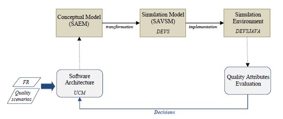
</span></font></p>            <p align="left" lang="en-US"><font face="Verdana" size="2">    <br>       </p>       <a name="f7"></a> </font>     ]]></body>
<body><![CDATA[<p align="center" lang="en-US"><font face="Verdana" size="2"><a name="f7"><img src="/img/revistas/cleiej/v14n3/3a04f7.jpg"></a></font></p>            <p style="margin-top: 0.21cm;" align="center"><font size="2" face="Verdana"><span lang="en-US"><b>Figure 7: </b>Quality attributes evaluation frame               using DEVS approach</span></font></p>            <p align="center" lang="en-US"><font face="Verdana" size="2">    <br>       </font>       </p>            <p style="margin-left: 0.5cm; text-indent: -0.5cm; margin-bottom: 0.21cm; text-align: left;" lang="en-US">  <font size="2" face="Verdana"><b>7             Case Study: A Classical Architectural Pattern</b></font></p>            <p align="justify"><font size="2" face="Verdana"><span lang="en-US">To illustrate the proposed model, a classical               architectural pattern is described. The <i>Pipe</i>               and <i>Filter</i> pattern is used to solve problems               related to the processing of data streams, where the decomposition               in subtasks are required to obtain a better result. The nature of               some kinds of systems requires an implementation based on               components, because the conversion of a data sequence is easier if               the task is divided in smaller parts rather than work with an only               component.</span></font></p>            <p align="justify"><font size="2" face="Verdana"><span lang="en-US">This pattern proposes two               types of elements: components called <i>Filters</i>               and connectors called <i>Pipes</i>. A pipe passes the information flow               from a filter to another filter, while the filter converts this               information to obtain a new flow adapted to the requirements of               the system. A filter can be connected to any number of input pipes               and to any number of output pipes (<a href="#f8">Fig. 8</a>).</span></font></p>            <p style="margin-top: 0.21cm;" align="center" lang="en-US">       <font face="Verdana" size="2">       <a name="f8"><img src="/img/revistas/cleiej/v14n3/3a04f8.gif" name="Imagen 1" align="bottom" border="0" height="104" width="324"></a></font></p>            <p style="margin-top: 0.21cm;" align="center"><font size="2" face="Verdana"><span lang="en-US"><b>Figure 8: </b>Conceptual model: Pipe and Filter pattern. </span></font>     </p>            <p style="text-indent: 0.64cm;" align="justify" lang="en-US">       <font face="Verdana" size="2">           ]]></body>
<body><![CDATA[<br>         </font>       </p>            <p align="justify"><font size="2" face="Verdana"><span lang="en-US">An example of the pipe and               filter pattern in a concrete application can be seen in <a href="#f9">Fig. 9</a>. We               restrict our treatment of the case study to elements that are               important to understand the concepts presented in this paper:               view, component, and responsibility. The connection mechanism (<i>Pipe</i>), in this example, only has the responsibility of               passing information from one filter to the next, so they are not               included in the example, but if we need a more detailed evaluation               they can be included in the model as instances of <i>CM</i>.</span></font></p>            <p align="justify" lang="en-US"><font size="2" face="Verdana">The license manager is a software management tool employed by           a software company and its end-user organizations with the purpose of           controlling when and how specific software products are able to be           used. </font> </p>            <p align="justify"><font size="2" face="Verdana"><span lang="en-US">The architectural view, as               shown in <a href="#f9">Fig. 9</a>, represents the client subsystem, which has three               components. The first component (<i>Decryptor</i>)               is in charge of decrypting the received file. Thus, an external               license file arrives to be processed. The plain text file contains               two main parts, license data and a digital firm. The license data               include customer name (organization), license date, days counter,               among others. The digital firm is encrypted, having inside a               unique identifier (hash). So, this component decrypts the firm               with the public key sending the file with this information to the               following component. The second component (<i>Authenticator</i>) receives the file and the identifier (hash). Then               it calculates, following an algorithm, the identifier (hash) using               the content of the file, and finally compares these two               identifiers. It sends the file and the result to the next               component. The last one (<i>Recorder</i>) receives the authenticated information               (file and result), and updates the license information in the DB               if the result is right, otherwise it blocks the user system               (error).</span></font></p>            <p align="justify"><font size="2" face="Verdana"><span lang="en-US">The architectural view, its               elements and their responsibilities are represented using UCM               (<a href="#f9">Fig. 9</a>). Responsibilities are extracted from the specified               functionalities representing executable units. Each component can               have assigned one or more responsibilities as follows: </span></font>     </p>            <p style="margin-top: 0.21cm;" align="justify"><font size="2" face="Verdana"><span lang="en-US"><i>Decryptor</i>:</span></font></p>            <p align="justify"><font size="2" face="Verdana"><span lang="en-US"><i>r1</i>: Receiving the license file</span></font></p>            <p align="justify"><font size="2" face="Verdana"><span lang="en-US"><i>r2</i>: Decrypting the digital firm with the public key               (from client side)</span></font></p>            <p style="margin-top: 0.21cm;" align="justify"><font size="2" face="Verdana"><span lang="en-US"><i>Authenticator</i>: </span></font> </p>            <p align="justify"><font size="2" face="Verdana"><span lang="en-US"><i>r3</i>: Authenticating data comparing the corresponding               information</span></font></p>            ]]></body>
<body><![CDATA[<p align="justify"><font size="2" face="Verdana"><span lang="en-US"><i>r4</i>: Sending the data with a report</span></font></p>            <p style="margin-top: 0.21cm;" align="justify"><font size="2" face="Verdana"><span lang="en-US"><i>Recorder</i>:</span></font></p>            <p align="justify"><font size="2" face="Verdana"><span lang="en-US"><i>r5</i>: Receiving the authenticated data </span></font>     </p>            <p align="justify"><font size="2" face="Verdana"><span lang="en-US"><i>r6</i>: Saving the corresponding data in a DB (information               about the correct or error data)</span></font></p>            <p align="justify" lang="en-US"><font face="Verdana" size="2">    <br>       </font>       </p>            <p align="justify"><font size="2" face="Verdana"><span lang="en-US">This model represents               architectural elements of the system adding functional aspects to them, considering not               only quality requirements but functional requirements. The               responsibilities have causal relationships. Stimulus begins an               execution flow obtaining a result as response.</span></font></p>            <p align="justify" lang="en-US"><font face="Verdana" size="2">    <br>       </font>       </p>            <p align="center" lang="en-US"><font face="Verdana" size="2"><a name="f9"><img src="/img/revistas/cleiej/v14n3/3a04f9.gif" name="Imagen 53" align="bottom" border="0" height="126" width="377"></a></font></p>            ]]></body>
<body><![CDATA[<p style="margin-top: 0.21cm;" align="center"><font size="2" face="Verdana"><span lang="en-US"><b>Figure 9: </b>UCM for the Pipe and Filter pattern application</span></font></p>            <p align="justify" lang="en-US"> </p>            <p align="justify"><font size="2" face="Verdana"><span lang="en-US">The software evaluation               concepts are translated into simulation elements. In <a href="#f10">Fig. 10</a>,               software structures are translated into DEVS models. In this way,               three types of elements are identified: view, simple component and               responsibilities. The process of transformation starts from atomic               to more complex structures (bottom-up viewpoint). First, the               responsibilities are the smallest structures where<i> Responsibility</i> concept in the conceptual model (<i>SAEM</i>) is transformed into <i>RM</i>               in the simulation model (<i>SAVSM</i>). So, each responsibility instance from               the software architectural model is translated into an instance of <i>RM</i> in the simulation model, where the               dynamic of it is defined by the functions described in the               previous sections. Responsibilities are connected by ports, with               the couplings for the given example, building more complex               structures. In this case, one of these more complex structures is               the <i>Filter</i>. So, each component that represents a <i>Filter</i> is translated into an instance of <i>SC</i> (<a href="#f10">Fig. 10</a>), with the corresponding input and output               ports, and assigned responsibilities (instances of <i>RM</i>).               Finally, the view is translated into a coupled DEVS too. This               simulation element has three instances of <i>SC</i>,               where each one has two instances of <i>RM</i>.               In this way, three levels of abstraction are represented in the               simulation model obtained from the software architecture of the               system that will be simulated.</span></font></p>            <p align="justify"><font size="2" face="Verdana"><span lang="en-US">The quantitative aspects               are reflected in the parameters of the models. In this case, the <i>execution_time</i> variable is a metric that could provide               information about the performance of the system during the               simulation. This value is calculated during the simulation for               each request processed by each responsibility.</span></font></p>            <p align="justify"><font size="2" face="Verdana"><span lang="en-US">
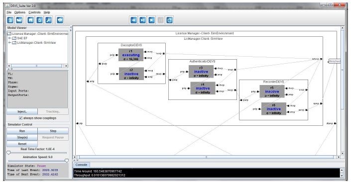
DEVS-Suite (2.0) is a               Parallel DEVS simulator with support for: automating design of               experiments in combination with animating models and generating               data trajectories at run-time. This environment allowed structural               validation of the simulation elements and the dynamic of each               element through manually tests. It provides tools for designing               and implementing experiments. In <a href="#f10">Fig. 10</a>, the architecture of the               system is represented using the proposed approach. Thus, the               specified DEVS hierarchy (<i>RM</i>, <i>SC</i>, <i>CM</i>, <i>SAVSM</i>) implemented using the classes provided               by DEVSJAVA library was integrated in this environment.</span></font></p>            <p align="justify" lang="en-US"><font face="Verdana" size="2">    <br>       </font>       </p>            <p style="margin-top: 0.21cm;" align="center" lang="es-AR">       </p>            <p align="center"><font size="2" face="Verdana"><span lang="en-US"><b><a name="f10" href="/img/revistas/cleiej/v14n3/3a04f10.jpg">Figure 10</a>: </b>DEVS-Suite view: simulation elements for the               architectural view of the example</span></font></p>            <p align="justify"><font size="2" face="Verdana"><span lang="en-US">The instances of the               simulation elements can be seen in the <i>Simulation View</i> (at top-right of the picture, <a href="#f10">Fig. 10</a>). The complete               simulation model (defined hierarchy of DEVS models) can be seen in               the <i>Model                 Viewer</i>               (top-left, <a href="#f10">Fig. 10</a>). Here we can see the composite elements and               their components. The other parts of the window are controls and               information for the simulation. For example, in the <i>Console</i> we can display the measured values for each               simulation element, or system indicators of the quality               attributes, such as the time around shown in <a href="#f10">Fig. 10</a>.</span></font></p>            ]]></body>
<body><![CDATA[<p align="justify" lang="en-US"><font size="2" face="Verdana">Software architecture evaluation has different goals:           detecting conflicts requirements, analyzing design decisions,           analyzing the impact of the changes, among others.</font></p>            <p align="justify"><font size="2" face="Verdana"><span lang="en-US">For example, for the               company may be important that the License system has a suitable               response because, otherwise the clients might be blocked affecting               their work. This process of validation must be efficient because               some systems are critics for the company. In this way, a               performance scenario is given as an example of the approach (it               can be specified following the template proposed by SEI <a href="#c17">[17]</a><a name="c17."></a>, as               shown in <a href="#f11">Fig. 11</a>, or in an informal form). In this scenario, time               around is analyzed for a normal operation of the system.</span></font></p>            <p align="justify" lang="en-US"><font face="Verdana" size="2">    <br>       </font>       </p>            <p align="center" lang="en-US"><font face="Verdana" size="2"><a name="f11"><img src="/img/revistas/cleiej/v14n3/3a04f11.gif" name="Marco2" alt="Marco2"></a></font></p>            <p style="margin-top: 0.21cm;" align="center"><font size="2" face="Verdana"><span lang="en-US"><b>Figure 11: </b>Example of quality scenario. Concrete scenario for               performance </span></font> </p>            <p align="justify" lang="en-US"><font face="Verdana" size="2">    <br>       </font>       </p>            <p align="justify"><font size="2" face="Verdana"><span lang="en-US">This approach allows               designers to study the system behavior, observing which components               are activated and which responsibilities are being preformed               inside of them (<i>Simulation                 View</i> in               DEVS-Suite), as shown in <a href="#f10">Fig. 10</a>. The state of each element is               indicated detecting which elements are executing and which are in               a passive state. The simulation of the system execution allows               evaluating quality scenarios related to the performance attribute               (in this approximation of the model). For example, in the previous               scenario we measure the time around in milliseconds, if the time               used to process the requests is too high, it can indicate some               problem. So the design has to be reviewed in detail, analyzing the               time per component or responsibility and detecting which of them               has some conflicts. This detection of elements provides               information to take some design decisions, such as the application               of architectural patterns, reallocation of responsibilities, or               addition of new components that reallocate the work load.</span></font></p>            <p align="justify"><font size="2" face="Verdana"><span lang="en-US">The design and               implementation of the experimental frame for evaluating software               architectures will include an automatic experimentation in the               simulation environment proposed in this work.</span></font></p>            ]]></body>
<body><![CDATA[<p style="text-indent: 0.64cm;" align="justify" lang="en-US">       <font face="Verdana" size="2">           <br>         </font>       </p>            <p style="margin-left: 0.5cm; text-indent: -0.5cm; margin-bottom: 0.21cm; text-align: left;" lang="en-US">  <font size="2" face="Verdana"><b>8             Discussion</b></font></p>            <p align="justify"><font size="2" face="Verdana"><span lang="en-US">In this paper we presented               a DEVS-based approach to               evaluate quality attributes that can be measured at runtime based               upon the software architecture of the system. Other approaches               have been proposed using different techniques for analyzing               different quality attributes. Some authors have classified them in               theoretical and empirical techniques <a href="#c8">[8]</a>, where we can include               three subclasses: one based on quality attributes, another one               based on software architecture, and the last one based on               scenarios. </span></font> </p>            <p align="justify"><font size="2" face="Verdana"><span lang="en-US">Most approaches are in the               first group being more theoretical. There are many methods based               on scenarios and focused on a more qualitative analysis than in               quantitative aspects <a href="#c18">[18]</a><a name="c18."></a>. Moreover, in the software architecture               area, several works propose ad-hoc assessment of the software               architecture qualities, but they introduce subjectivity and               ambiguity in the assessment <a href="#c1">[1]</a>.</span></font></p>            <p align="justify"><font size="2" face="Verdana"><span lang="en-US">Other alternatives are               mainly focused on quality attributes. For example, Markov Process               has been used to evaluate the reliability, performance and               security of a system (<a href="#c2">[2]</a>, <a href="#c3">[3]</a>). Also, other contributions have               employed Queueing Theory to measure performance <a href="#c5">[5]</a>. Petri Nets               are other option, which has been applied to evaluate different               quality attributes such as security, performance and reliability               <a href="#c4">[4]</a>. Finally, the SEI (Software Engineering Institute) has made               some contributions to deal with architecture evaluation (a               software named <i>ArchE</i>), using Fixed Priority Scheduling to               measure performance and Graph Theory to analyze modifiability               (<a href="#c19">[19]</a>, <a href="#c20">[20]</a>, <a href="#c21">[21]</a>).<a name="c19."></a><a name="c20."></a><a name="c21."></a></span></font></p>            <p align="justify"><font size="2" face="Verdana"><span lang="en-US">The experience indicates               that Markov               Process seems to be a good approximation for evaluating software               architectures; many works have shown how an architectural model               can be traduced into a Markov chain. Nevertheless, this approach               presents two situations which have to be improved: the               representation of the states that only include components from the               architectural model, losing other important aspects of the               architectural domain, and the analytical resolution of the models               which requires specific information (such as transition               probabilities, quantitative data for each component, etc) <a href="#c22">[22]</a>.<a name="c22."></a>               Queueing Theory provides a good performance assessment, but it is               difficult to represent other aspects of the software quality such               as: security, reliability, etc. Petri Nets have limitations to               model some situations such as priorities and complex system which               imply problems to solve the net (known problem of Petri Nets).               This problem requires simplification, but this mechanism implies               to lose concepts that may be important to represent the real               problem (system that is being simulated), affecting the final               results. </span></font> </p>            <p align="justify"><font size="2" face="Verdana"><span lang="en-US">The various approaches for               the software quality evaluation presented previously provide a quantitative analysis focuses               on specific quality attributes. They are based on mathematical               fundamentals which are important for the consideration of final               results. However, these techniques have the disadvantage of being               too restrictive from the modeling point of view. They have some               limitations to represent a number of situations about the               real-world systems and they incorporate the complexities of the               technique in the model, losing abstraction capabilities. Some               critical studies have shown limitations of this kind of techniques               (i.e. works focused on reliability prediction techniques such as               <a href="#c22">[22]</a>).</span></font></p>            <p align="justify"><font size="2" face="Verdana"><span lang="en-US">Many authors have exposed               the enterprise needs and they have emphasized the importance of               the functional aspects in the architectural evaluation, the               increasing complexity of the systems and the performance as               dominating quality attribute.</span></font></p>            <p align="justify"><font size="2" face="Verdana"><span lang="en-US">In this context, empirical               techniques have increasing importance. Architectural prototyping               has been proposed in this area to analyze: structural               (components), communicational (connectors), and quality aspects               (performance, security) <a href="#c8">[8]</a>. However, the wasted effort to               prototype the software and the initial costs have a major impact               than other proposals. Furthermore, prototypes do not include               functional aspects.</span></font></p>            ]]></body>
<body><![CDATA[<p align="justify"><font size="2" face="Verdana"><span lang="en-US">There are few contributions               that include               functionality in the architectural models and in the automatic               evaluation. UCM provides a form to add behavior to abstract               structures, but it is an informal notation <a href="#c6">[6]</a>. However,               formalisms such as Queueing Theory have been proposed to               complement it in the analysis of performance<a href="#c7"> [7]</a>, but lead to the               same matters that have previously explained. </span></font>     </p>            <p align="justify"><font size="2" face="Verdana"><span lang="en-US">Simulation is another               empirical technique. It allows exploring structural and behavioral               aspects as well as quality indicators without implementation               costs. In this way, we present a novel approach, from a conceptual               model to a formalism that is more general than Petri Net and               Queueing theory. DEVS is based on the system theory, so it allows               clear abstractions and models and a modular construction, reducing               the complexity of the systems using a hierarchical approximation.               The building of simulation blocks, from basic models (atomic DEVS)               to complex models (coupled DEVS), allows a suitable representation               of the architectural structures, manipulating parameters for a               quantitative analysis of the quality aspects. Furthermore, DEVS               formalism is embedded in a simulation framework <a href="#c9">[9]</a>. This frame               defines three entities and their relationships, uncoupling the               model from the simulator. Thus, the complexity of the simulator is               kept outside the model, and the model is closer to the real               system. It is more expressive, allowing the definition of               domain-specific components and providing major semantic to the               models (in this case, elements related to the software               architecture and its quality).</span></font></p>            <p align="justify"><font size="2" face="Verdana"><span lang="en-US">Discrete event simulation               applied to measure quality attributes using the software               architecture of the system has the following items to be analyzed:               i) it provides an overview of the performance of the system, ii)               it allows a study of the behavior of the system and its elements               (components and connectors with their responsibilities               respectively), iii) its outputs include measures, such as               throughput and time around, iv) it is a flexible approach, and it               could be adapted to new situations, such as adding other quality               aspects to be considered in the evaluation. </span></font>     </p>            <p align="justify"><font size="2" face="Verdana"><span lang="en-US">The last one is the most               important feature because is the most difference from other               techniques. DEVS is known for its capability to model complex               systems without losing efficiency in the implementation of the               simulation. The system theory fundamentals of DEVS are powerful               tools to manage the complexities of the software architecture               elements. It provides a high level of abstraction and scalability               too, which are not found in other techniques. One limitation of               this approach, also presented in others, might be the input data               behavior employed by the model (probability distributions) for               obtaining better results (metrics), because the lack of historical               data is an important problem in the software industry. </span></font>     </p>            <p align="justify" lang="en-US"><font face="Verdana" size="2">    <br>       </font>       </p>            <p style="margin-bottom: 0.21cm; text-align: left;" lang="en-US">       <font size="2" face="Verdana"><b>9 Conclusion</b></font></p>            <p align="justify"><font size="2" face="Verdana"><span lang="en-US">The paper proposed an approach based on DEVS that introduces               modular simulation into software architecture evaluation at early               stage of the software development. Firstly, a conceptual model to               evaluate software architectures has been formulated. The model               represents information related to the system structure and               behavior, and includes other concepts that enable quantitative               analysis to validate several scenarios. Also, it incorporates the <i>Responsibility</i> concept, which provides a way to               include functional aspects, representing the software execution               flow, unlike other approaches that only focus on non-functional               requirements (quality attributes).</span></font></p>            <p align="justify"><font size="2" face="Verdana"><span lang="en-US">We proposed the use of DEVS formalism to incorporate               the advantages of discrete event simulation in the context of               architectural design. This formalism builds simulation elements in               a modular and hierarchical way. Furthermore, a framework for               modeling and simulation supports this formalism, keeping the model               decoupled from the complexity of the simulator and from the               experimental frame. These features provide flexibility, making               easy to incorporate new elements in the simulation model and               encapsulating the environment of the studied system under the               concept of experimental frame. </span></font> </p>            <p align="justify"><font size="2" face="Verdana"><span lang="en-US">We considered performance               as initial quality attribute measurable at runtime, because it is               a dominating quality attribute in many systems. Nevertheless, the               proposal is more ambitious in order to incorporate other quality               attributes indicators. For example, availability could require a               new state (to simulate a software failure) in the atomic DEVS (RM)               and the corresponding metrics (i.e. unavailability time). In this               way, the simulation model specified using DEVS provides               scalability with a formal support. </span></font> </p>            ]]></body>
<body><![CDATA[<p align="justify"><font size="2" face="Verdana"><span lang="en-US">DEVS-Suite has facilitated               a concrete simulator and a set of tools to implement the               simulation model and its elements. This environment allowed the               design of simple experiments which have been manually executed to               test the proposed simulation model (structure and behavior using               animation). We believe that the experimental framework of the               simulation is a very important part for the results (quality               metrics), so we are planning to do an exploratory study of its               development, designing and implementing a specific experimental               frame that responds suitably to different quality goals. </span></font>     </p>            <p align="justify"><font size="2" face="Verdana"><span lang="en-US">As regards the simulation model that we proposed,               it could be of interest in future work to include complex               architectural concepts such as architectural patterns and               composite components besides required parameters for the quality               metrics (atomic elements).</span></font></p>            <p align="justify"><font size="2" face="Verdana"><span lang="en-US">Finally, translating               architectural concepts into simulation elements requires models               transformation.               MDA (Model-driven Architecture) framework will be applied, because               of the importance of models in this process. The transformation               rules that describe how one or more elements of the source model               (architectural view) can be transformed into one or more elements               in the target model (simulation model -DEVS), are currently               defined in a simple and non-standardized form, and they have to be               applied manually. In future works, automatic transformation will               be integrated, formalizing the rules and studying standards that               are widely used such as QVT (Query, Views, and Transformations)               and MOF (Meta Object Facility) proposed by OMG.</span></font></p>            <p align="justify" lang="en-US"> </p>            <p style="margin-right: 0.02cm; margin-top: 0.42cm; margin-bottom: 0.21cm; page-break-inside: avoid; page-break-after: avoid;" align="left" lang="en-US">  <font face="Verdana" size="2"><b>Acknowledgements</b></font></p>            <p align="justify"><font size="2" face="Verdana"><span lang="en-US">The authors thank the </span><span lang="en-GB">financial</span><span lang="en-US"> support received from <i>Universidad                 Tecnol&Atilde;&sup3;gica Nacional</i>               (25/O118 &acirc;&euro;&ldquo; UTI1083) and <i>Agencia Nacional                 de Promoci&Atilde;&sup3;n </i> </span><span lang="en-GB"><i>Cient&Atilde;&shy;fica</i></span><span lang="en-US"><i> y Tecnol&Atilde;&sup3;gica</i> (PAE-PICT 02315).</span></font></p>     <p align="justify"></p>         <font face="Verdana" size="2"><b>References</b> </font>                   <p style="margin-bottom: 0.21cm; widows: 2; orphans: 2;" lang="en-US">  <font face="Verdana" size="2"><a name="c1"></a><a href="#c1.">1</a>. M. Galster, A. Eberlein and M.             Moussavi, &acirc;&euro;&oelig;Early Assessment of Software Architecture Qualities&acirc;&euro;&#65533;, in             <i>Proc. Research Challenges in Information Science (RCIS 2008)</i>,             2008, pp. 81-86.</font></p>                            <p style="margin-bottom: 0.21cm; widows: 2; orphans: 2;" lang="en-US"> <font face="Verdana"><a name="c2"><font size="2"></font></a></font> <font size="2"><span style="font-family: Verdana;"><a href="#c2.">2</a>. </span> </font><font size="2" face="Verdana">W.-L. Wang, D. Pan and M.-H. Chen,             &acirc;&euro;&oelig;Architecture-based software reliability modeling&acirc;&euro;&#65533;, <a class="western" href="http://www.sciencedirect.com/science/journal/01641212"><i>Journal                 of Systems and Software</i></a>, <a class="western" href="http://www.sciencedirect.com/science?_ob=PublicationURL&amp;_tockey=%23TOC%235651%232006%23999209998%23615329%23FLA%23&amp;_cdi=5651&amp;_pubType=J&amp;view=c&amp;_auth=y&amp;_acct=C000050221&amp;_version=1&amp;_urlVersion=0&amp;_userid=10&amp;md5=9bb20dfed157b304b65b1093340a5152">vol.               79, Issue 1</a>, pp. 132-146, January 2006.</font></p>                                 <p style="margin-bottom: 0.21cm; widows: 2; orphans: 2;" lang="en-US">  <font face="Verdana" size="2"><span class="western"><a name="c3"></a><a href="#c3.">3</a>. V. Sharma</span>             and <span class="western">K. </span>Trivedi, &acirc;&euro;&oelig;Quantifying software             performance, reliability and security: An architecture-based             approach&acirc;&euro;&#65533;, <i>Journal of Systems and Software</i>, vol. 80, Issue             4, pp. 493-509, April 2007.</font></p>                            ]]></body>
<body><![CDATA[<p style="margin-bottom: 0.21cm; widows: 2; orphans: 2;" lang="en-US">  <font face="Verdana" size="2"><a name="c4"></a><a href="#c4.">4</a>. K. Fukuzawa and M. Saeki, &acirc;&euro;&oelig;Evaluating             software architecture by coloured Petri Nets&acirc;&euro;&#65533;, in <i>Proc. 14th               International Conference on Software Engineering and Knowledge               Engineering</i>, 2002, pp. 263- 270.</font></p>                            <p style="margin-bottom: 0.21cm; widows: 2; orphans: 2;" lang="en-US">  <font face="Verdana" size="2"><a name="c5"></a><a href="#c5.">5</a>. B. Spitznagel and D. Garlan,             &acirc;&euro;&oelig;Architecture-based performance analysis&acirc;&euro;&#65533;, in <i>Proc. 1998               Conference on Software Engineering and Knowledge Engineering</i>,             1998, pp. 146-151.</font></p>                            <p style="margin-bottom: 0.21cm; widows: 2; orphans: 2;" lang="en-US">  <font face="Verdana" size="2"><a name="c6"></a><a href="#c6.">6</a>. D. Amyot and G. Mussbacher, &acirc;&euro;&oelig;User             Requirements Notation: The First Ten Years, The Next Ten Years&acirc;&euro;&#65533;, <i>Journal               of Software</i>, vol. 6, N&Acirc;&deg; 5, pp. 747-768, May 2011.</font></p>                            <p style="margin-bottom: 0.21cm; widows: 2; orphans: 2;" lang="en-US">  <font face="Verdana" size="2"><a name="c7"></a><a href="#c7.">7</a>. D. Petriu and M. Woodside, &acirc;&euro;&oelig;Software             performance models from system scenarios in Use Case Maps&acirc;&euro;&#65533;, <i>Lecture               Notes in Computer Science</i>, <i>Proc. 12th International               Conference on Computer Performance Evaluation, Modelling               Techniques and Tools</i>, vol. 2324, pp. 141-158, 2002. </font> </p>                            <p style="margin-bottom: 0.21cm; widows: 2; orphans: 2;" lang="en-US">  <font face="Verdana" size="2"><a name="c8"></a><a href="#c8.">8</a>. H. Christensen and K. Hansen, &acirc;&euro;&oelig;An             empirical investigation of architectural prototyping&acirc;&euro;&#65533;, <i>Journal               of Systems and Software</i>, vol. 83 Issue 1, pp. 133-142, January             2010.</font></p>                            <p style="margin-bottom: 0.21cm; widows: 2; orphans: 2;" lang="en-US">  <font face="Verdana" size="2"><a name="c9"></a><a href="#c9.">9</a>. B. Zeigler, H. Praehofer and T. Kim, <i>Theory               of Modeling and Simulation&acirc;&euro;&ldquo;Integrating Discrete Event and               Continuous Complex Dynamic Systems</i>, Academic Press, 2000.</font></p>                            <p style="margin-bottom: 0.21cm; widows: 2; orphans: 2;" lang="en-US">  <font face="Verdana" size="2"><a name="c10"></a><a href="#c10.">10</a>. R. Wojcik, F. Bachmann, L. Bass, P.             Clements, P. Merson, R. Nord and B. Wood, &acirc;&euro;&oelig;Attribute-Driven Design             (ADD)&acirc;&euro;&#65533;, SEI, Version 2.0. Technical report, CMU/SEI-2006-TR-023,             ESC-TR-2006-023, 2006.</font></p>                            <!-- ref --><p style="margin-bottom: 0.21cm; widows: 2; orphans: 2;" lang="en-US">  <font face="Verdana" size="2"><a name="c11"></a><a href="#c11.">11</a>. ISO/IEC WD3 42010. IEEE P42010/D3.             Systems and Software Engineering. Recommended practice for             architectural description of software-intensive systems, 2008.    </font></p>                            <!-- ref --><p style="margin-bottom: 0.21cm; widows: 2; orphans: 2;" lang="en-US">  <font face="Verdana" size="2"><a name="c12"></a><a href="#c12.">12</a>. C. Hofmeister, R. Nord and D. Soni, <i>Applied               Software Architecture</i>, Addison-Wesley, 2000.    </font></p>                            <p style="margin-bottom: 0.21cm; widows: 2; orphans: 2;" lang="en-US">  <font face="Verdana" size="2"><a name="c13"></a><a href="#c13.">13</a>. R. Buhr, &acirc;&euro;&oelig;Making behaviour a concrete             architectural concept&acirc;&euro;&#65533;, in <i>Proc. 32nd Hawaii International               Conference on System Sciences</i>, 1999, pp. 1-5.</font></p>                            <!-- ref --><p style="margin-bottom: 0.21cm; widows: 2; orphans: 2;" lang="en-US">  <font face="Verdana" size="2"><a name="c14"></a>14. R. Wirfs-Brock and A. McKean, <i>Object               Design: Roles, Responsibilities and Collaborations</i>,             Addison-Wesley, 2002.    </font></p>                            <p style="margin-bottom: 0.21cm; widows: 2; orphans: 2;" lang="en-US">  <font face="Verdana" size="2"><a name="c15"></a><a href="#c15.">15</a>. A. <span class="western">Verbraeck </span>             and E. <span class="western">Valentin, </span> &acirc;&euro;&oelig;Design guidelines             for simulation building blocks&acirc;&euro;&#65533;, in <i>Proc. 2008 Winter Simulation               Conference (WSC)</i>, December 2008, pp. 923&acirc;&euro;&ldquo;932.</font></p>                            <!-- ref --><p style="margin-bottom: 0.21cm; widows: 2; orphans: 2;" lang="en-US">  <font face="Verdana" size="2"><a name="c16"></a><a href="#c16.">16</a>. B. Zeigler and H. Sarjoughian<i>, Introduction               to DEVS Modeling and Simulation with JAVA: Developing               Component-based Simulation Models</i>, 2005.    </font></p>                            <!-- ref --><p style="margin-bottom: 0.21cm; widows: 2; orphans: 2;" lang="en-US">  <font face="Verdana" size="2"><span lang=""><a name="c17"></a><a href="#c17.">17</a>. L. Bass, P. Clements and               R. Kazman, <i>Software Architecture in                 Practice</i>, Addison-Wesley, 2003.    </span></font></p>                            <!-- ref --><p style="margin-bottom: 0.21cm; widows: 2; orphans: 2;" lang="en-US">  <font face="Verdana" size="2"><span lang=""><a name="c18"></a><a href="#c18.">18</a>. P. </span>Clements<span lang="">, R. Kazman and M. Klein, <i>Evaluating                 Software Architectures: Methods and Case Studies</i>, Addison-Wesley, 2002.    </span></font></p>                            <p style="margin-bottom: 0.21cm; widows: 2; orphans: 2;" lang="en-US">  <font face="Verdana" size="2"><a name="c19"></a><a href="#c19.">19</a>. F. Bachmann, L. Bass and M. Klein,             &acirc;&euro;&oelig;Preliminary design of ArchE: a software architecture design             assistant&acirc;&euro;&#65533;, SEI, Technical Report, CMU/SEI-2003-TR-021,             ESC-TR-2003-021, 2003.</font></p>                            <p style="margin-bottom: 0.21cm; widows: 2; orphans: 2;" lang="en-US">  <font face="Verdana" size="2"><a name="c20"></a><a href="#c20.">20</a>. F. Bachmann, L. Bass, M. Klein, J.             McGregor and P. Bianco, &acirc;&euro;&oelig;Using ArchE in the classroom: one             experience&acirc;&euro;&#65533;, Software Architecture Technology Initiative, Technical             Note, CMU/SEI-2007-TN-001, 2007. </font> </p>                            <p style="margin-bottom: 0.21cm; widows: 2; orphans: 2;" lang="en-US">  <font face="Verdana" size="2"><a name="c21"></a><a href="#c21.">21</a>. F. Bachmann, L. Bass and M. Klein,             &acirc;&euro;&oelig;Experience using an expert system to assist an architect in             designing for modifiability&acirc;&euro;&#65533;, in <i>Proc. Fourth Working IEEE/IFIP               Conference on Software Architecture (WICSA 2004)</i>, 2004, pp.             281-284. </font> </p>                            <p style="margin-bottom: 0.21cm; widows: 2; orphans: 2;" lang="en-US">  <font face="Verdana" size="2"><a name="c22"></a><a href="#c22.">22</a>. L. K. Singh, A. K. Tripathi and G.             Vinod, &acirc;&euro;&oelig;Software reliability early prediction in architectural             design phase: Overview and Limitations&acirc;&euro;&#65533;, <i>Journal of Software               Engineering and Applications</i>, vol. 4 N&Acirc;&deg; 3, pp.181-186, March             2011.</font></p>         <font face="Verdana" size="2">             <br>                            </font>                                <div id="sdfootnote1">            <p><font face="Verdana"><a class="sdfootnotesym" name="sdfootnote1sym" href="#sdfootnote1anc"> <font size="2">1</font></a><font style="font-size: 10pt;" size="1"><span lang="en-US"> SWAG: Software Architecture Group. <a href="http://www.swag.uwaterloo.ca/swagkit/">http://www.swag.uwaterloo.ca/swagkit/</a></span></font></font></p>       </div>            <div id="sdfootnote2">            <p><font face="Verdana"><a class="sdfootnotesym" name="sdfootnote2sym" href="#sdfootnote2anc"> <font size="2">2</font></a><font style="font-size: 10pt;" size="1"><span lang="en-US"> DEVS-Suite. <a href="http://www.acims.arizona.edu/SOFTWARE/software.shtml">http://www.acims.arizona.edu/SOFTWARE/software.shtml</a></span></font></font></p>       </div>            ]]></body>
<body><![CDATA[<div type="FOOTER">            <p style="margin-bottom: 0.21cm;" lang="en-US"> <font face="Verdana" size="2">     <br>               <br>         </font>         </p>       </div>           ]]></body><back>
<ref-list>
<ref id="B1">
<label>1</label><nlm-citation citation-type="">
<person-group person-group-type="author">
<name>
<surname><![CDATA[Galster]]></surname>
<given-names><![CDATA[M]]></given-names>
</name>
<name>
<surname><![CDATA[Eberlein]]></surname>
<given-names><![CDATA[A]]></given-names>
</name>
<name>
<surname><![CDATA[Moussavi]]></surname>
<given-names><![CDATA[M]]></given-names>
</name>
</person-group>
<article-title xml:lang="en"><![CDATA[Early Assessment of Software Architecture Qualities]]></article-title>
<source><![CDATA[Proc. Research Challenges in Information Science (RCIS 2008)]]></source>
<year>2008</year>
<page-range>81-86</page-range></nlm-citation>
</ref>
<ref id="B2">
<label>2</label><nlm-citation citation-type="journal">
<person-group person-group-type="author">
<name>
<surname><![CDATA[Wang]]></surname>
<given-names><![CDATA[W.-L]]></given-names>
</name>
<name>
<surname><![CDATA[Pan]]></surname>
<given-names><![CDATA[D]]></given-names>
</name>
<name>
<surname><![CDATA[Chen]]></surname>
<given-names><![CDATA[M.-H]]></given-names>
</name>
</person-group>
<article-title xml:lang="en"><![CDATA[Architecture-based software reliability modeling]]></article-title>
<source><![CDATA[Journal of Systems and Software]]></source>
<year>Janu</year>
<month>ar</month>
<day>y </day>
<volume>79</volume>
<numero>1</numero>
<issue>1</issue>
<page-range>132-146</page-range></nlm-citation>
</ref>
<ref id="B3">
<label>3</label><nlm-citation citation-type="journal">
<person-group person-group-type="author">
<name>
<surname><![CDATA[Sharma]]></surname>
<given-names><![CDATA[V]]></given-names>
</name>
<name>
<surname><![CDATA[Trivedi]]></surname>
<given-names><![CDATA[K]]></given-names>
</name>
</person-group>
<article-title xml:lang="en"><![CDATA[Quantifying software performance, reliability and security: An architecture-based approach]]></article-title>
<source><![CDATA[Journal of Systems and Software]]></source>
<year>Apri</year>
<month>l </month>
<day>20</day>
<volume>80</volume>
<numero>4</numero>
<issue>4</issue>
<page-range>493-509</page-range></nlm-citation>
</ref>
<ref id="B4">
<label>4</label><nlm-citation citation-type="confpro">
<person-group person-group-type="author">
<name>
<surname><![CDATA[Fukuzawa]]></surname>
<given-names><![CDATA[K]]></given-names>
</name>
<name>
<surname><![CDATA[Saeki]]></surname>
<given-names><![CDATA[M]]></given-names>
</name>
</person-group>
<article-title xml:lang="en"><![CDATA[Evaluating software architecture by coloured Petri Nets]]></article-title>
<source><![CDATA[]]></source>
<year></year>
<conf-name><![CDATA[ Proc. 14th International Conference on Software Engineering and Knowledge Engineering]]></conf-name>
<conf-date>2002</conf-date>
<conf-loc> </conf-loc>
</nlm-citation>
</ref>
<ref id="B5">
<label>5</label><nlm-citation citation-type="confpro">
<person-group person-group-type="author">
<name>
<surname><![CDATA[Spitznagel]]></surname>
<given-names><![CDATA[B]]></given-names>
</name>
<name>
<surname><![CDATA[Garlan]]></surname>
<given-names><![CDATA[D]]></given-names>
</name>
</person-group>
<article-title xml:lang="en"><![CDATA[Architecture-based performance analysis]]></article-title>
<source><![CDATA[]]></source>
<year></year>
<conf-name><![CDATA[ Proc. 1998 Conference on Software Engineering and Knowledge Engineering]]></conf-name>
<conf-date>1998</conf-date>
<conf-loc> </conf-loc>
</nlm-citation>
</ref>
<ref id="B6">
<label>6</label><nlm-citation citation-type="journal">
<person-group person-group-type="author">
<name>
<surname><![CDATA[Amyot]]></surname>
<given-names><![CDATA[D]]></given-names>
</name>
<name>
<surname><![CDATA[Mussbacher]]></surname>
<given-names><![CDATA[G]]></given-names>
</name>
</person-group>
<article-title xml:lang="en"><![CDATA[User Requirements Notation: The First Ten Years, The Next Ten Years]]></article-title>
<source><![CDATA[Journal of Software]]></source>
<year>May </year>
<month>20</month>
<day>11</day>
<volume>6</volume>
<numero>5</numero>
<issue>5</issue>
<page-range>747-768</page-range></nlm-citation>
</ref>
<ref id="B7">
<label>7</label><nlm-citation citation-type="confpro">
<person-group person-group-type="author">
<name>
<surname><![CDATA[Petriu]]></surname>
<given-names><![CDATA[D]]></given-names>
</name>
<name>
<surname><![CDATA[Woodside]]></surname>
<given-names><![CDATA[M]]></given-names>
</name>
</person-group>
<article-title xml:lang="en"><![CDATA[Software performance models from system scenarios in Use Case Maps: Lecture Notes in Computer Science]]></article-title>
<source><![CDATA[]]></source>
<year></year>
<conf-name><![CDATA[ Proc. 12th International Conference on Computer Performance Evaluation, Modelling Techniques and Tools]]></conf-name>
<conf-loc> </conf-loc>
</nlm-citation>
</ref>
<ref id="B8">
<label>8</label><nlm-citation citation-type="journal">
<person-group person-group-type="author">
<name>
<surname><![CDATA[Christensen]]></surname>
<given-names><![CDATA[H]]></given-names>
</name>
<name>
<surname><![CDATA[Hansen]]></surname>
<given-names><![CDATA[K]]></given-names>
</name>
</person-group>
<article-title xml:lang="en"><![CDATA[An empirical investigation of architectural prototyping]]></article-title>
<source><![CDATA[Journal of Systems and Software]]></source>
<year>Janu</year>
<month>ar</month>
<day>y </day>
<volume>83</volume>
<numero>1</numero>
<issue>1</issue>
<page-range>133-142</page-range></nlm-citation>
</ref>
<ref id="B9">
<label>9</label><nlm-citation citation-type="book">
<person-group person-group-type="author">
<name>
<surname><![CDATA[Zeigler]]></surname>
<given-names><![CDATA[B]]></given-names>
</name>
<name>
<surname><![CDATA[Praehofer]]></surname>
<given-names><![CDATA[H]]></given-names>
</name>
<name>
<surname><![CDATA[Kim]]></surname>
<given-names><![CDATA[T]]></given-names>
</name>
</person-group>
<source><![CDATA[Theory of Modeling and Simulation-Integrating Discrete Event and Continuous Complex Dynamic Systems]]></source>
<year>2000</year>
<publisher-name><![CDATA[Academic Press]]></publisher-name>
</nlm-citation>
</ref>
<ref id="B10">
<label>10</label><nlm-citation citation-type="">
<person-group person-group-type="author">
<name>
<surname><![CDATA[Wojcik]]></surname>
<given-names><![CDATA[R]]></given-names>
</name>
<name>
<surname><![CDATA[Bachmann]]></surname>
<given-names><![CDATA[F]]></given-names>
</name>
<name>
<surname><![CDATA[Bass]]></surname>
<given-names><![CDATA[L]]></given-names>
</name>
<name>
<surname><![CDATA[Clements]]></surname>
<given-names><![CDATA[P]]></given-names>
</name>
<name>
<surname><![CDATA[Merson]]></surname>
<given-names><![CDATA[P]]></given-names>
</name>
<name>
<surname><![CDATA[Nord]]></surname>
<given-names><![CDATA[R]]></given-names>
</name>
<name>
<surname><![CDATA[Wood]]></surname>
<given-names><![CDATA[B]]></given-names>
</name>
</person-group>
<collab>CMU/SEI</collab>
<source><![CDATA[Attribute-Driven Design (ADD): SEI, Version 2.0. Technical report]]></source>
<year>2006</year>
</nlm-citation>
</ref>
<ref id="B11">
<label>11</label><nlm-citation citation-type="">
<source><![CDATA[Systems and Software Engineering: Recommended practice for architectural description of software-intensive systems]]></source>
<year>2008</year>
</nlm-citation>
</ref>
<ref id="B12">
<label>12</label><nlm-citation citation-type="book">
<person-group person-group-type="author">
<name>
<surname><![CDATA[Hofmeister]]></surname>
<given-names><![CDATA[C]]></given-names>
</name>
<name>
<surname><![CDATA[Nord]]></surname>
<given-names><![CDATA[R]]></given-names>
</name>
<name>
<surname><![CDATA[Soni]]></surname>
<given-names><![CDATA[D]]></given-names>
</name>
</person-group>
<source><![CDATA[Applied Software Architecture]]></source>
<year>2000</year>
<publisher-name><![CDATA[Addison-Wesley]]></publisher-name>
</nlm-citation>
</ref>
<ref id="B13">
<label>13</label><nlm-citation citation-type="confpro">
<person-group person-group-type="author">
<name>
<surname><![CDATA[Buhr]]></surname>
<given-names><![CDATA[R]]></given-names>
</name>
</person-group>
<article-title xml:lang="en"><![CDATA[Making behaviour a concrete architectural concept]]></article-title>
<source><![CDATA[]]></source>
<year></year>
<conf-name><![CDATA[ in Proc. 32nd Hawaii International Conference on System Sciences]]></conf-name>
<conf-date>1999</conf-date>
<conf-loc> </conf-loc>
</nlm-citation>
</ref>
<ref id="B14">
<label>14</label><nlm-citation citation-type="book">
<person-group person-group-type="author">
<name>
<surname><![CDATA[Wirfs-Brock]]></surname>
<given-names><![CDATA[R]]></given-names>
</name>
<name>
<surname><![CDATA[McKean]]></surname>
<given-names><![CDATA[A]]></given-names>
</name>
</person-group>
<source><![CDATA[Object Design: Roles, Responsibilities and Collaborations]]></source>
<year>2002</year>
<publisher-name><![CDATA[Addison-Wesley]]></publisher-name>
</nlm-citation>
</ref>
<ref id="B15">
<label>15</label><nlm-citation citation-type="">
<person-group person-group-type="author">
<name>
<surname><![CDATA[Verbraeck]]></surname>
<given-names><![CDATA[A]]></given-names>
</name>
<name>
<surname><![CDATA[Valentin]]></surname>
<given-names><![CDATA[E]]></given-names>
</name>
</person-group>
<article-title xml:lang="en"><![CDATA[Design guidelines for simulation building blocks]]></article-title>
<source><![CDATA[Proc. 2008 Winter Simulation Conference (WSC)]]></source>
<year>Dece</year>
<month>mb</month>
<day>er</day>
<page-range>923-932</page-range></nlm-citation>
</ref>
<ref id="B16">
<label>16</label><nlm-citation citation-type="">
<person-group person-group-type="author">
<name>
<surname><![CDATA[Zeigler]]></surname>
<given-names><![CDATA[B]]></given-names>
</name>
<name>
<surname><![CDATA[Sarjoughian]]></surname>
<given-names><![CDATA[H]]></given-names>
</name>
</person-group>
<source><![CDATA[Introduction to DEVS Modeling and Simulation with JAVA: Developing Component-based Simulation Models]]></source>
<year>2005</year>
</nlm-citation>
</ref>
<ref id="B17">
<label>17</label><nlm-citation citation-type="book">
<person-group person-group-type="author">
<name>
<surname><![CDATA[Bass]]></surname>
<given-names><![CDATA[L]]></given-names>
</name>
<name>
<surname><![CDATA[Clements]]></surname>
<given-names><![CDATA[P]]></given-names>
</name>
<name>
<surname><![CDATA[Kazman]]></surname>
<given-names><![CDATA[R]]></given-names>
</name>
</person-group>
<source><![CDATA[Software Architecture in Practice]]></source>
<year>2003</year>
<publisher-name><![CDATA[Addison-Wesley]]></publisher-name>
</nlm-citation>
</ref>
<ref id="B18">
<label>18</label><nlm-citation citation-type="book">
<person-group person-group-type="author">
<name>
<surname><![CDATA[Clements]]></surname>
<given-names><![CDATA[P]]></given-names>
</name>
<name>
<surname><![CDATA[Kazman]]></surname>
<given-names><![CDATA[R]]></given-names>
</name>
<name>
<surname><![CDATA[Klein]]></surname>
<given-names><![CDATA[M]]></given-names>
</name>
</person-group>
<source><![CDATA[Evaluating Software Architectures: Methods and Case Studies]]></source>
<year>2002</year>
<publisher-name><![CDATA[Addison-Wesley]]></publisher-name>
</nlm-citation>
</ref>
<ref id="B19">
<label>19</label><nlm-citation citation-type="">
<person-group person-group-type="author">
<name>
<surname><![CDATA[Bachmann]]></surname>
<given-names><![CDATA[F]]></given-names>
</name>
<name>
<surname><![CDATA[Bass]]></surname>
<given-names><![CDATA[L]]></given-names>
</name>
<name>
<surname><![CDATA[Klein]]></surname>
<given-names><![CDATA[M]]></given-names>
</name>
</person-group>
<source><![CDATA[Preliminary design of ArchE: a software architecture design assistant]]></source>
<year>2003</year>
</nlm-citation>
</ref>
<ref id="B20">
<label>20</label><nlm-citation citation-type="">
<person-group person-group-type="author">
<name>
<surname><![CDATA[Bachmann]]></surname>
<given-names><![CDATA[F]]></given-names>
</name>
<name>
<surname><![CDATA[Bass]]></surname>
<given-names><![CDATA[L]]></given-names>
</name>
<name>
<surname><![CDATA[Klein]]></surname>
<given-names><![CDATA[M]]></given-names>
</name>
<name>
<surname><![CDATA[McGregor]]></surname>
<given-names><![CDATA[J]]></given-names>
</name>
<name>
<surname><![CDATA[Bianco]]></surname>
<given-names><![CDATA[P]]></given-names>
</name>
</person-group>
<source><![CDATA[Using ArchE in the classroom: one experience]]></source>
<year>2007</year>
</nlm-citation>
</ref>
<ref id="B21">
<label>21</label><nlm-citation citation-type="confpro">
<person-group person-group-type="author">
<name>
<surname><![CDATA[Bachmann]]></surname>
<given-names><![CDATA[F]]></given-names>
</name>
<name>
<surname><![CDATA[Bass]]></surname>
<given-names><![CDATA[L]]></given-names>
</name>
<name>
<surname><![CDATA[Klein]]></surname>
<given-names><![CDATA[M]]></given-names>
</name>
</person-group>
<article-title xml:lang="en"><![CDATA[Experience using an expert system to assist an architect in designing for modifiability]]></article-title>
<source><![CDATA[]]></source>
<year></year>
<conf-name><![CDATA[ Proc. Fourth Working IEEE/IFIP Conference on Software Architecture (WICSA 2004)]]></conf-name>
<conf-date>2004</conf-date>
<conf-loc> </conf-loc>
</nlm-citation>
</ref>
<ref id="B22">
<label>22</label><nlm-citation citation-type="journal">
<person-group person-group-type="author">
<name>
<surname><![CDATA[Singh]]></surname>
<given-names><![CDATA[L. K]]></given-names>
</name>
<name>
<surname><![CDATA[Tripathi]]></surname>
<given-names><![CDATA[A. K]]></given-names>
</name>
<name>
<surname><![CDATA[Vinod]]></surname>
<given-names><![CDATA[G]]></given-names>
</name>
</person-group>
<article-title xml:lang="en"><![CDATA[Software reliability early prediction in architectural design phase: Overview and Limitations]]></article-title>
<source><![CDATA[Journal of Software Engineering and Applications]]></source>
<year>Marc</year>
<month>h </month>
<day>20</day>
<volume>4</volume>
<numero>3</numero>
<issue>3</issue>
<page-range>181-186</page-range></nlm-citation>
</ref>
</ref-list>
</back>
</article>
