


Servicios Personalizados
Revista

Articulo
 Inglés (pdf)
 Articulo en XML
 Referencias del artículo
Links relacionados
Compartir

 Permalink
CLEI Electronic Journal
versión On-line ISSN 0717-5000
CLEIej vol.19 no.2 Montevideo ago. 2016
Configurable Web Warehouses construction through BPM Systems
Andrea Delgado, Adriana Marotta
Universidad de la República, Facultad de Ingeniería
Montevideo, Uruguay
{adelgado, amarotta}@fing.edu.uy
Abstract
The process of building Data Warehouses (DW) is well known with well defined stages but at the same time, mostly carried out manually by IT people in conjunction with business people. Web Warehouses (WW) are DW whose data sources are taken from the web. We define a flexible WW, which can be configured accordingly to different domains, through the selection of the web sources and the definition of data processing characteristics. A Business Process Management (BPM) System allows modeling and executing Business Processes (BPs) providing support for the automation of processes. To support the process of building flexible WW we propose a two BPs level: a configuration process to support the selection of web sources and the definition of schemas and mappings, and a feeding process which takes the defined configuration and loads the data into the WW. In this paper we present a proof of concept of both processes, with focus on the configuration process and the defined data.
Abstract in Spanish
El proceso de construir Almacenes de Datos (Data Warehouses, DW) es bien conocido con etapas bien definidas pero al mismo tiempo, es realizado mayormente en forma manual por personas de TI en conjunto con personas del negocio. Los almacenes de datos de la Web (Web Warehouses, WW) son DW cuyas fuentes de datos son tomadas de la web. Definimos un WW flexible, que puede ser configurado según distintos dominios, mediante la selección de fuentes de datos y de las características del procesamiento de los datos. Un Sistema de Gestión de Procesos de Negocio (Business Process Management System, BPMS) permite modelar y ejecutar Procesos de Negocio (PNs) proveyendo soporte a la automatización de procesos. Para soportar el proceso de construcción de WW flexibles proponemos dos niveles de PNs: un proceso de configuración para soportar la selección de las fuentes de datos de la web y la definición de esquemas y mapeos, y un proceso de carga que toma la configuración definida y carga los datos en el WW. En este artículo presentamos una prueba de concepto de ambos procesos, con foco en el proceso de configuración y los datos definidos.
Keywords: Data Warehouse (DW), Web Warehouse (WW), Business Process Management Systems (BPMS), Business Process modeling and execution
Keywords in Spanish: Data Warehouse (DW), Web Warehouse (WW), Business Process Management Systems (BPMS), Modelado y ejecución de Procesos de Negocio
Received: 2015-11-09 Revised 2016-04-25 Accepted 2016-07-29
DOI: http://dx.doi.org/10.19153/cleiej.19.2.8
1 Introduction
In last years the amount of data generated on the web has grown considerably, being one of the current key challenges to be able to effectively collect and analyze it, in order to gain usable information. In this context, Web Warehouses (WW) are Data Warehouses (DW) whose data sources are taken from the web. They are a valuable tool for analysis and decision making based for example, on open government data [1], in many different areas. We define a flexible WW, which can be configured accordingly to different domains, through the selection of the corresponding web sources and the definition of data processing characteristics. This WW is implemented through a general platform that is configured for each domain, or particular case it will be used. The general platform is built according to an architecture that is suitable for different Wws [2]. Although the process of building DW is well known with well defined stages, it is still mostly carried out manually by IT people in conjunction with business people.
Business Process Management Systems (BPMS) [3] provide tool support for the Business Process Management (BPM) [3][4][5] vision in organizations. This kind of software integrates different tools to support the complete BPs lifecycle [3], mainly modeling BPs and executing them in a compatible process engine. One of the many benefits associated with this vision is that BP models provide an explicitly view on which activities are performed to reach the organization goals, how things are done by whom, when they are done, and which artifacts are used and generated. Nowadays, one of the most used notations for modeling and executing BPs is the Business Process Model and Notation (BPMN 2.0) [6] standard from OMG, which provides not only a notation for modeling BPs but also a defined semantic for its elements, making it also executable. Also, it is easily understandable by business people and it has been embraced both at the academic and industry level as a way to communicate between business and IT people [7].
Based on the previous analysis, we propose a two Business Process (BPs) level vision to help define and automate the process of building flexible WW: at the first level, a configuration process to support the selection of web sources and the definition of schemas and mappings, which is mostly carried out manually, and at the second level, a feeding process that takes the defined configuration and loads the data into the WW, which is performed mostly automatically. Both the configuration and the feeding processes are modeled as BPs in the BPMN 2.0 notation and executed in the BPMS Activiti [8]. The main reasons for selecting this tool were that it implements the BPMN 2.0 standard and it is open source. In previous work [9] we have presented the initial idea of building a Quality-aware WW with BPs in BPMN 2.0, and since then we have split the proposal into two projects mainly corresponding to the two processes defined: the configuration process, which we have worked on last year, and the feeding process based on configuration data, adding quality data to both processes, in which we are working now. Data quality is taken into account when building the WW, to obtain information about the quality of data provided to the user, and to improve quality of data throughout the WW process.
This paper extends [10], where we presented the complete configuration process along with the analysis and decisions we have made to provide automated support to the configuration BP and data that will be used by the feeding process in order to effectively load the WW. We also presented a proof of concept of the feeding process to validate the configuration BP by means of an example with open data from Uruguay regarding the "Tourism" domain. In this article we extend previous work, presenting in more detail the definition of the configuration database (metadata) and the relation between the configuration process and the tables of this database, we include a new application example (we have carried out in order to provide extra validation of the configuration process) with open data from the United Kingdom regarding the "Transport" domain, and we extend the related work with two more proposals we had not included before (due to space restrictions). The new application example allows us to claim that the configuration process we have defined is able to cover different data sets from different domains, countries and languages, providing support for the definition of the elements needed to build flexible WW.
The main contributions of our work are: (i) the definition and conceptual models in BPMN 2.0 of both the configuration and feeding processes to support the construction of flexible WW, (ii) the definition of the configuration metadata, which allow the semi-automatic feeding process of the WW, (iii) the complete implementation of the configuration process in the Activiti BPM platform and a proof of concept of the feeding process, to show the feasibility of our approach, and (iv) the realization of two examples of application with open data from Uruguay and the UK, in different languages and from different domains, to show how our proposal supports the construction of flexible WW in an automated way.
The rest of the document is organized as follows: in section II we present some concepts regarding WW, BPs and BPMS, in section III we describe in detail the BPs we have defined to support the WW building process, in section IV we present two examples of application with open data to illustrate the use of our proposal, in section V we discuss related work and finally in section VI we present some conclusions and current and future work.
2. WW and Business Processes
In this section we introduce concepts regarding WW and BPs that are used throughout the proposal.
2.1 Processes to build flexible WWs
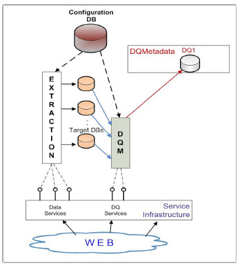
The WW we define is a system that consists of several components and is service oriented. Fig. 1 shows its architecture. The system components are in charge of the main tasks that are necessary to adequately process web data and provide them to the user for analysis. These tasks are always present in this kind of systems, but there are many aspects of them that should be solved and implemented in different ways, according to the needs of the particular case. An effective mechanism for encapsulating the solution to the different aspects, is through the utilization of specialized services. The utilization of services facilitates the configuration of the system, contributing to the flexibility of its building.
Figure 1: Web Warehouse General Architecture
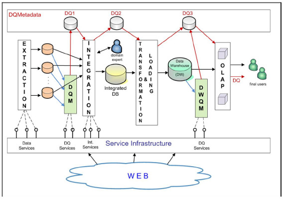
The system components are: Extraction, Integration, Transformation & Loading, OLAP (On-Line Analytical Processing), Data Quality Measurement (DQM) and DW Quality Measurement (DWQM). The Service Infrastructure layer offers the different available specialized services, which include data services, data quality services and integration services. The Extraction component must solve the problem of format heterogeneity, since data can be found in a variety of formats, such as csv, html, xml, rdf, etc. It must be able to extract from each source a pre-defined set of items and store them into a database, assuring that each data item goes to the right place. The Integration component must perform the integration of data coming from the different web sources, solving the problems of entity resolution and data conflicts, with the presence of semantic heterogeneity. The Transformation & Loading component transforms data to the multidimensional model, preparing them to OLAP manipulation. The OLAP component manages the data cubes allowing the multidimensional data analysis through front-end utilities. DQM component is in charge of measuring data quality of data that have been just extracted from the web, while DWQM component is in charge of measuring data quality of the DW. These components register data quality information in the databases DQ1, DQ2, and DQ3, which contain quality information about the WW data (DQMetadata).
The described components base their solutions on the invocation of the services offered by the Service Infrastructure layer. DQMetadata is read by the WW processes in order to take quality issues into account when treating data. On the other hand, it is written by them for enabling the propagation of the quality metadata throughout the different stages of the data transformation. This is necessary in order to maintain the correspondence between quality information and WW data, when WW data is combined and transformed.
As previously explained, the flexible WW we propose consists of a configurable platform, such that, in order to build a specific WW, two phases must be carried out: the configuration phase and the feeding phase.
In the configuration phase different activities are applied in order to configure each WW component. The main configuration activities for the Extraction component are: (1) selecting domain and web sources, (2) defining the sources schemas, (3) defining data mappings, and (4) selecting data services for sources data extraction. For the Integration component, they are: (1) integrated schema definition, (2) schema mappings specifications, and (3) selecting integration services. The Transformation & Loading component configuration consists in the implementation of the transformation process, while OLAP component configuration is done by defining the OLAP cubes. Finally, the main configuration activities for DQM and DWQM components are: (1) defining data quality model for extracted data, (2) defining data quality model for DW data, (3) defining data quality metadata, and (4) selecting data quality services.
In the feeding phase the WW configured components will automatically load and build the specific WW, executing the corresponding extraction, integration and transformation processes, managing data quality throughout the building process.
2.2 BPs, BPMN 2.0 and BPM Systems
BPs provide an horizontal vision of the organization, showing explicitly the sequence of activities and different options of execution that are performed to provide value to the business in an organizational and technical environment [3]. BPM [3][4][5] provides the means to support this horizontal vision based on the BPs lifecycle [3] and different tools integrated in BPMS, to help carrying out the activities that are defined within each phase. The core of these BPMS is a process engine, which allows executing the BP model driving the execution of the system, in which are known as Process Aware Information Systems (PAIS) [10]. Since the definition of workflows in the nineties decade and web services in early two thousands, the definition and execution of processes has been carried out in languages such as XPDL [12] and WS-BPEL [13], among other proposals. BPMN 2.0 allows not only modeling BPs with a notation that is understood by business people, but also executing the same model, helping to minimize errors from requirements to development, and helping business and IT people to work together. BPMN 2.0 defines elements that are needed to model BPs, including activities (sub-processes and tasks), gateways (AND, XOR, OR), events (time, message, etc.), swimlanes (pools and lanes), data, connectors, among others.
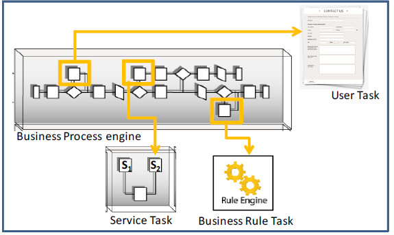
Regarding BPs execution in BPMS, the process engine that executes BP models can be seen as an intermediate layer between the user interface (mostly a Web Portal) and the implementation of the BP (mostly in Java with elements from the Java world). The process engine then controls, at any given time, which activity is done by whom, presenting the corresponding elements to the user (managing the so called working list) and/or performing the invocations to classes, following the defined BP's control flow. In the case of user tasks, the execution of the process engine will send it and present it to the inbox associated with the defined role (or user, depending on the assignment, e.g. algorithms for load balancing or other criteria). In the case of automated tasks, the execution of the process engine will perform the invocations to the classes, external systems, Web Services (WS) or other defined components, such as a business rules engine. In Fig. 2 we present examples for different execution scenarios in a process engine: user task, service task and business rule task.
Figure 2: Different types of execution in a BPMS
3. Automated Support for the WW Configuration
The configuration BP is a key step in building a flexible WW, in which the user defines all the data that will be used in the feeding process to actually generate the WW. The configuration data is registered by the system in our own data model in which we have defined key elements we need to further generate the WW.
3.1 WW Configuration Process
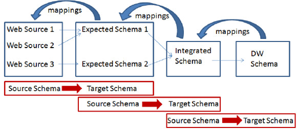
The aim of the configuration process of the WW is to gather from the user and register in the configuration database, the data that will allow carrying out the ETL for the DW in the feeding process. Then, defining the WW configuration involves things such as selecting the web sources from which to gather the data, defining the schemas that will be used (expected schema, integrated schema and data warehouse schema), as well as the mappings between their elements that are needed to guide the extraction, selection and integration of data in each step of the feeding process. The WW configuration process we have defined is mainly focused on supporting the definition of schemas and correspondences between their elements as shown in Fig. 3.
Figure 3: Definition of schemas and their correspondence
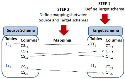
We define a conceptual sub-process that will be used throughout the configuration BP for each schema creation and corresponding mappings, in which in the first place, the user is asked to define the target schema, and then to define the corresponding mappings to the origin schema (or file in the case of the web sources). Fig. 4 shows graphically this conceptual sub-process.
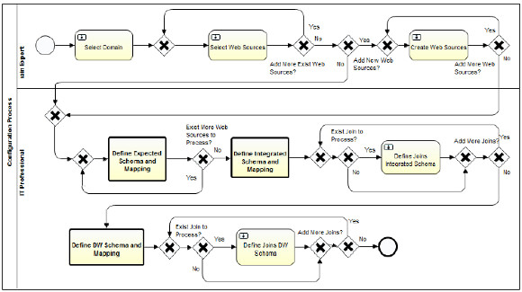
Fig. 5 presents the WW configuration process specified in BPMN 2.0 and implemented in the Activiti BPMS. When modeling it we follow the modeling guides in [14], e.g. balancing gateways with one to bifurcate the flow and another at the end to join it again, using verbs in infinitive form to name the activities (Select instead of selection), among others. We also apply several workflow patterns as defined in [15].
Figure 4: Conceptual process to define schemas and mappings
The configuration process model in Fig. 5 defines two lanes one for the Domain Expert and the other for the IT professional, which are responsible for the activities defined. The first three tasks correspond to: 1) "Select Domain" for the selection of the WW domain, 2) "Select Web Source" for the selection of existing web sources already registered for the selected domain, and 3) "Create Web Source" for the creation and register of new web sources for the selected domain. Some key domains and corresponding web sources will be already registered in the configuration database for the users to select. If when defining the configuration for a WW the user considerers that the existing web sources are enough, indicating so in the corresponding task 2), the creation of new web sources for the domain will be skipped.
Once these tasks are finished, the system has registered the WW domain and the associated web sources that will provide the data for the WW. The rest of the configuration process will define the way in which the data will be extracted from the web sources, the different schemas that will be defined and used within the process steps, along with the corresponding mappings to select and/or integrate the data.
Figure 5: WW configuration process specified in BPMN 2.0 and implemented in Activiti BPMS
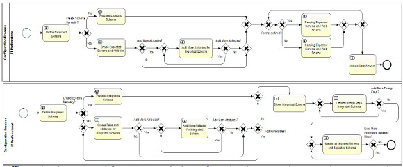
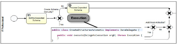
The first definition of schemas and mappings is encapsulated in the sub-process 4) "Define expected Schema and mapping", which follows the conceptual process as shown in Fig. 4. In this sub-process, for each selected web source the expected schema into which the extracted data will be loaded is defined, along with the corresponding mappings between fields in the web source file and attributes in the expected schema. This sub-process is shown in Fig. 6(a), where three options to define and use an expected schema are provided. In the first place, an existing expected schema can be selected, the second option allows the user to create it automatically uploading a JSON file containing the definition of the schema, and finally, creating the schema from scratch manually by the user. To do so, data regarding the table name, attribute name and type, for each element defined has to be entered. To continue the loop the flag "Add More Attributes" can be marked, until there are no more attributes and/or tables to define.
In the three options, the expected schema that is created is associated with the selected web source for the current configuration. In the first and second options, the automated task "Process expected schema" is executed, to perform the association or to parse the JSON file to create the expected schema and the association, in the third case the user must define the expected schema in a loop that can be executed until the user indicates to finish the creation. In any case the expected schema must have a name, attributes and their types.
Following the conceptual process shown in Fig. 4, the next step is to define the mappings between the expected schema and the selected web source. To do so, two options are provided: if the web source has a format that is known by the system (e.g. HTML, CSV) the user is presented with the existing column names in the file, if the format is not known by the system, then the user has to manually register each column of the web source file. In any case, the correspondence between columns in the expected schema and columns in the web source has to be defined manually by the user in the task "Mapping expected schema and web source". At the end of the sub-process, the task "Upload Data service" allows the user to define the Data Service (DS) in charge of actually extracting the data from the selected web source in the feeding process. The user form will show a default DS (registered in the system for the format of the selected web source) and the user will be able to change it by selecting another URL for the DS.
The next definition of schemas and mappings correspond to the integrated schema to join the data from the web sources, which is encapsulated in the sub-process 5) "Define integrated schema and mapping" and shown in Fig. 6(b). To do so, the user has to create each table and the corresponding attributes, which again can be done automatically by uploading a JSON with the schema or manually defining each table and attributes in a loop, until the user selects to finish the creation. For each table the primary keys are marked, generating an initial definition of the Integrated Schema, which is then shown to the user and afterwards with this information, the foreign keys can be marked for each table to finish the creation of the schema.
Figure 6: Sub-process to define: (a) expected schemas for each web source and corresponding mappings, (b) integrated schema
At this point we have defined the web sources from where to extract the data which will be placed into the Expected Schemas and then will be joined into the Integrated Schema. To do so and following the conceptual process as presented in Fig. 4, to end with these definitions, the user has to define the mappings between the Expected Schema for each web source and the Integrated Schema that he/she has just defined. To define the mappings, the system will show the user a form containing the Integrated Schema tables and their attributes which the user should associate with the corresponding attributes from the defined Expected Schemas. This is done in a loop until all attributes of all tables in the Integrated Schema has been mapped. In this case other information has to be gathered from the user, regarding which joins are needed between which Expected Schemas tables, to be able to load the data into the Integrated Schema during the feeding process. The task 6) "Define joins Integrated Schema" allows the user to define this information.
The final step involves the definition of the DW Schema, from the tables defined in the Integrated Schema. This is done in the sub-process 7) "Define DW Schema and mapping" which also follows the conceptual process as presented in Fig. 4 and is analogous to the definition of the Integrated Schema shown in Fig. 6(b). In this case, apart from defining each table and the corresponding attributes (which again can be done automatically by uploading a JSON with the schema or manually defining each table and attributes in a loop), the user has to mark which tables are fact tables and which ones are dimension tables. After that, for each table the primary keys are marked, generating an initial definition of the DW Schema, which is then shown to the user and afterwards with this information, the foreign keys can be marked for each fact table to finish the creation of the DW schema. In this case other information is also required, regarding the joins that are needed between the tables in the defined Integrated Schema to be able to load the data into the corresponding ones in the DW Schema in the feeding process. The task 8) "Define joins DW Schema" allows the user to define this information, as in the previous one.
3.2 Configuration database (metadata)
The configuration data that is gathered from the user along the configuration process is stored as metadata in the Configuration Database in our own defined data model, to be read during the feeding process to guide it. In Fig. 7 we present some of the key tables, attributes and relationships we have defined in our configuration data model.
Figure 7: Key tables defined in the configuration data model
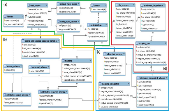
As it can be seen in Fig. 7, at the center of the definitions in the (a) group there is a table named "Configuration" to hold the data for each configuration, with an id and the domain selected by the user, which are also defined in another table. Tables are grouped in the four key steps defined by the configuration process: (a) the initial step for the definition of the configuration, the domain, the corresponding web sources and format, (b) the definition of the expected schemas and the mapping with the selected web sources, (c) the definition of the integrated schema and the mapping with the defined expected schemas and finally (d) the definition of the DW schema and the mapping with defined integrated schema. So key defined tables refer to the source and target schemas in each moment of the configuration BP (i.e. web sources, expected schemas, integrated schema and DW schema), and the mappings between them that will allow to automate the load of the corresponding data in the feeding process.
As an example of each triple defined for the schema and mappings (source schema, target schema and mapping), in Fig. 7(d) it can be seen that the resulting DW Schema is registered in the Table "dw_schema" which has as attributes the name for the Schema, the reference to the configuration and the name of each table defined, with the mark of fact table or not. The table "atributes_dw_schema" defines each attribute within each table in the schema, referring the previous table primary key, and adding the name of each attribute defined in each table. This pair of tables models the target schema in this last triple. The source table corresponds to the Integrated Schema and is defined in the same way in the "integrated_schema" and "atributes_integrated_schema" tables.
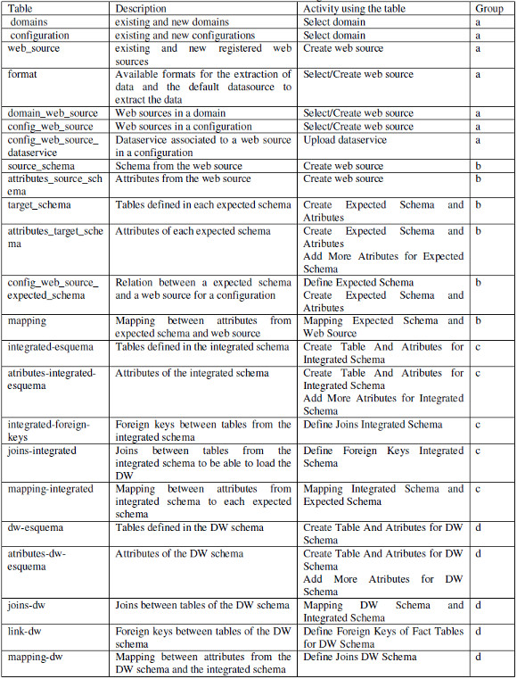
Finally, the mapping is stored in the table "mapping_dw" which refers to each attribute tables (source and target) in the corresponding configuration. As model in the configuration BP following the conceptual process presented in Fig. 4, mappings are defined at the attribute level between each attribute of the target schema to attributes in the source schema, until all have been defined. This same design applies for the mapping regarding the triple Integrated Schema, Expected Schemas and mapping between them, and similarly (adding some extra needed elements) regarding the triple Expected Schema, Web Sources and mapping between them. In Table I we present each defined table including a description of its content, in which activity of the configuration process the table is referred (to select existing data to be showed to the user or to insert data gathered from the user), referencing the group of Fig. 7 where it is located if showed.
Table I: Metadata tables defined in the configuration database
3.3 WW feeding process using configuration data
Once the configuration process has finished, all the relevant configuration data is stored in the Configuration Database. At this stage, the WW is ready to be generated and fed. In the feeding process each component is executed as shown in Fig. 1, but the first step each one executes is the query to the Configuration Database. Fig. 8 shows the examples of the Extraction and the Data Quality Measurement (DQM) processes.
Figure 8: WW Feeding – Extraction and DQM example
In the case of the Extraction process, it extracts from the Configuration Database the data sources URLs, the identification of the data services that extract data from these URLs, and the expected schema that has to be filled and stored in the target databases. In the case of the DQM process, it queries the Configuration Database in order to obtain the data quality model (quality dimensions and metrics to be applied), the data quality services to invoke, and the data quality metadata identification. The quality data is not yet integrated into the configuration process. Analogously, the other components obtain the needed information from the Configuration Database and execute the corresponding data processing. However, the feeding process is not yet completely defined as there are many data integration issues that need to be addressed to complete its automation.
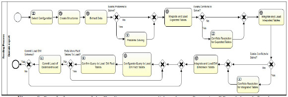
Fig. 9 shows the proof of concept of the Feeding process we have developed in order to validate the configuration BP and data defined. It can be seen that differently to the configuration BP, most tasks in this process are automatic of type service task, and only a few remain of type user task. This is due to the focus of the process in reading the already registered configuration data, create the needed schemas and perform the Extraction, Transformation and Load (ETL) processes in order to automatically generate the DW. Most of the user tasks are defined to present information to the user in case of integration problems, execution problems and to approve the generation of the final DW schema and data load.
Figure 9: Proof of concept of the Feeding process to validate the configuration BP and data defined
3.4 Implementation of the Configuration process
To implement both the configuration and feeding process models we used the Activiti BPM platform, as mentioned before. Since we followed the same conceptual definitions for both processes, we focus here on the implementation of the configuration process since the feeding process is at initial stages. Activiti allows defining a java layer below the models to manage the different elements and events involved in BPs execution. Based on the architecture of Activiti we have designed our software layer based on conceptual packages and following best design practices and patterns. In Fig. 10 we present the diagram of the system logic.
Figure 10: Diagram of the system logic showing layers and packages organization
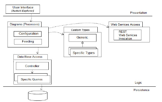
For the user interface we used the already implemented web portal from the Activiti BPM platform, the Activiti-explorer web application. The package Diagrams includes the configuration and feeding process models diagrams, the corresponding XML files, and the main java classes used to extend the behavior of the process. The CustomTypes package includes the implementation of specific types we defined for managing custom data, and the Web Services Access package includes the invocation of the services defined in the services layer, to carry out several functions such as extracting data from web sources, loading data into the schemas, etc.
The configuration process as presented in Figure 5 is defined based on business activities (user task, automated tasks, etc.) in which the domain context is to build a data warehouse, so as business terminology we use the concepts of tables, primary and foreign keys, mappings between attributes, and so on. To be able to show data to the user and gather the needed data from the user, and register it in the configuration data base, we need to add some technical information to the configuration process. We believe that business processes should stay in the context of the business, without making explicit the technical aspects that we need to add in order to implement them, that is not to add automatic activities with names like "obtain values for combo box" before a user task, or "insert into the database" after a user task or "calculate values for some parameter" as an automated task, among others. In this sense, our approach is to hide these technical details inside the events that are triggered in the execution of each activity (tasks and sub-processes), that is the start event at the beginning of the activity, the complete event at the end of the activity, and the execution of the activity itself, depending on the type of task being implemented. In Figure 11 we show this approach for the implementation of UserTasks within the configuration process, and in Figure 12 we present the implementation of automated ServiceTasks.
Figure 11: Approach for the implementation of the configuration process shown in Fig. 5 - UserTasks
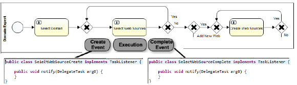
Figure 12: Approach for the implementation of the configuration process shown in Fig. 5 - ServiceTasks
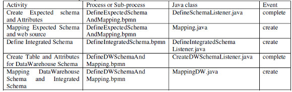
For the implementation of UserTasks, listeners for these events are used to be able to select and insert data into the configuration data base, and for the implementation of automated ServiceTasks, apart from the listeners for these events, the execution of the task itself must be implemented. Since Activiti BPMS provides total and easy integration with the java world, the implementation of processes involves using the Eclipse IDE and very well-known things such as defining java classes that are "hooked" in the execution of the process in the extension points that the engine itself provides. In Table 2 we present an example of java classes that are executed within selected activities of the process, indicating to which process it belongs (configuration process or corresponding sub-process) and to which event it is associated, as described before.
Table 2: Example of java classes executed from the activities and associated events
4. Examples of application with Open Data
In this section we present two examples of application which we used mainly to evaluate the configuration process, and a prototype of the feeding process which we used to validate the load of DW reading the data provided by it to the configuration database.
4.1 "Tourism" domain from Uruguay
There is a considerable amount of information published as open government data in the Tourism domain, in Uruguay. Several datasets that contribute to touristic information, published by different organisms, can be found. In this case we generate a WW where data about events in different places of the country are analyzed together with data about accommodation and transport useful for assistants to the events. The analysis may be done by dates. The analysis indicators are the quantity of events and the quantity of accommodation places. Fig. 13 presents the conceptual multidimensional model for this analysis, following the model of [16]. As most of the available data is in Spanish we will present the equivalence between the concepts from the design of the WW presented here and the ones actually used in the execution of the processes, when needed.
Figure 13: Conceptual multidimensional model for Events fact
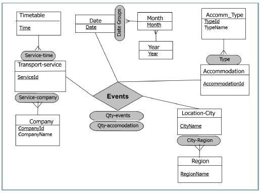
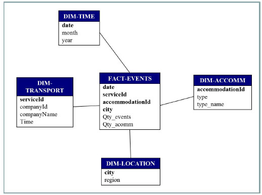
The dimensions in this DW are: (i) Transport-service, with two hierarchies (Service-time and Service-company), each one containing two levels, (ii) Accommodation, with one hierarchy (Type), containing two levels, (iii) Location-city, with one hierarchy (City-Region) of two levels, and (iv) Date, with one hierarchy (Date groups) which contains three levels. The DW measures are Qty-events and Qty-accommodation. Fig. 14 presents the logical schema of the target DW.
Figure 14: Logical DW schema
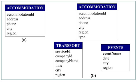
The main data sources are open data publications from public organisms, although some data (proportionally very few) had to be generated by us. Accommodation data are obtained from publications of the Government Agency of Tourism and Sport (original name: “Ministerio de Turismo y Deporte”) [17], transport data from publications of the National Transport Unit (original name: “Dirección Nacional de Transporte”) [18], some data about events are obtained from publications of Municipality of Durazno City (original name: “Intendencia de Durazno”) [19]. We describe in detail the Accommodation data processing starting from the web sources. The selected Accommodation data was about Hotels, Hostels and Campings. These three datasets are published in three different web pages of the same site. The data published in the three cases are: identifier, name, address, city, region, phone, cellular phone, web, mail, coordinates. In the case of Hotels they also publish a category data item.
For our WW we define the expected schema shown in Fig. 15(a). This is the expected schema for the three sources, i.e. it specifies the data we require from each of these sources. Mappings between the expected schema attributes and the web sources items are defined during the configuration phase such that the loading from the sources to the target databases can be performed. For example, accommodation is mapped to the identifier of the hotels source data, and analogously with the hostels and campings sources. The whole integrated schema is shown in Fig. 15(b). Note that in this schema, Accommodation table has a new attribute named type, which will contain one of the values: “hotel”, “hostel” and “camping”.
Figure 15: (a) Expected schema for Accommodation data, (b) Logical Integrated schema
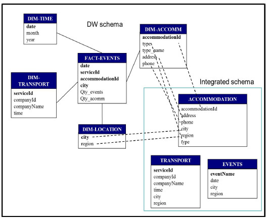
Integrated schema attributes are mapped to expected schema attributes as shown in Fig. 16. In this case the attribute called type is not mapped. In the feeding phase the value for this attribute will be asked to the user.
Figure 16: Mappings between Integrated and Expected schema

In addition, mappings between the Integrated schema and the DW schema must be performed. Fig. 17 shows only the mappings between the Accommodation table attributes and the DW attributes due to visualization restrictions. Fact-events attributes’ mappings are as follows:
-
date -> Events.date,
-
serviceId -> Transport.serviceId,
-
accommodationId -> Accommodation.acommodationId,
-
city -> Accommodation.city,
-
city -> Events.city,
-
city -> Transport.city.
It is important to note that the city attribute of the DW schema is mapped to the three tables of the Integrated schema. This is especially important for the feeding phase, since the city determines which combinations of transport service, accommodation and events must be generated.
Figure 17: Mappings between the DW and the Integrated schema
A.Execution of the WW Configuration process
As an example of the execution of the WW Configuration process we have implemented, we present some screenshots of the forms defined to input the configuration data by the user. In the first place, after selecting the domain for the current configuration, the user selects the Web Sources that will be used to extract the data to feed the DW. In Fig. 18(a) the corresponding Activiti form for the user task is presented, showing the possible selection of existing Web Sources for the seleected domain such as Accomodation (hotels_web, hostels_web, campings_web), Events (events_web not shown), Transport (transport_web not shown), and Regions (departaments_web) which finally was not selected.
Figure 18: Activiti forms screenshots: (a) Select Web Sources for the selected domain and (b) Create Expected schema for each selected Web Source
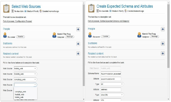
As it can be seen, we present five Web Sources per form (due to Activiti limitations) and the option to continue selecting (which is not shown) to perform the loop and present again the form. We also provide the options for creating new and/or adding existing Web Sources. After selecting the Web Sources, as defined in the configuration BP, the Data Sources are provided, the Expected Schemas and corresponding mappings to the Web Sources are defined. To create the Expected Schemas, a form is presented to the user to define the attributes and corresponding types, as shown in Fig. 18(b). As it can be seen, for each Web Source an Expected Schema has to be created, from scratch or selecting already existing ones. In this case we show the selection of the Web Sources "hoteles_web", "hostels_web" and "campings_web", which will be mapped to the Expected Schema Accomodation (Accommodation_expected) as presented in Fig. 15. We present in each form five attributes to be defined with their name and type, and the option to continue creating attributes which will activate the loop and present the form again, for the same Web Source until it is finished. In this screenshot the options to select existing schemas and to continue adding attributes are not shown, but they are the same as in the previous form. Once the expected schemas are created, the mappings with each Web Source are defined.
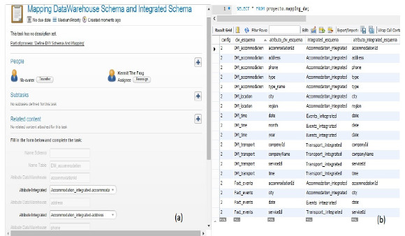
Then the Integrated Schema is defined in the same way, and after that, the corresponding mappings to the Expected Schemas defined are established, as presented in Fig. 16. Finally the DW Schema is defined, creating the tables and defining which are fact tables and which are dimension tables. To end the configuration process, the corresponding mappings from the DW to the Integrated Schema are defined. As all mappings are presented in the same way, in Fig. 19 we show the definition of mappings between the DW Schema and the Integrated Schema as an example, along with the data registered in the "mapping_dw" table after executing the task.
It can be seen in Fig. 19(a) that for each Table in the DW Schema, we present all the attributes defined, which have to be mapped to attributes in the tables of the Integrated Schema. In this case, the DW table corresponds to the DW_accommodation one with attributes "accommodationId" and "address", and the Integrated attributes correspond also to the table Accomodation_integrated with the same names. In Fig. 19(b) an example of the data registered in the "mapping_dw" table after executing the task "Mapping DW schema and Integrated Schema" is shown. It presents the complete set of values for the configuration in the following columns: config, dw_schema, attribute_dw_schema, integrated_schema and attribute_integrated_schema, as defined in the configuration data model presented in Fig. 7. Once the Configuration process has finished, the configuration data has been registered in the Configuration database filling the tables presented in Fig. 7, and the Feeding process to actually load the data into the WW can be executed.
Figure 19: (a) Activiti form to define mappings between the DW schema and the Integrated schema, (b) corresponding data in the "mapping_dw" table
B.Execution of the WW Feeding process
To validate the configuration BP and data we have defined, the proof of concept developed for the Feeding process was executed in order to analyze the WW generated. The first form asks the user to select a defined Configuration, in this case the one we have defined, and based on that the process is executed automatically. For each Feeding process a new data base is created with the name "base_id" being "id" the number of the selected configuration. Then the Expected Schemas, the Integrated and the DW schemas are created as defined in the configuration data, with corresponding tables and attributes.
Then the data is extracted from the Web Sources via invoking the Data Sources defined, and loaded into the Expected Schemas as defined. Continuing with the automated process, the data is loaded in the Integrated Schema following the definitions of mappings and joins, and then into the DW Schema as defined. In this case we do not have any integration issues since we have simplified the data to execute the basic scenario of DW loading. The only form that will be presented to the user during the process correspond to the confirmation of the query generated to load the DW fact tables, giving the user the option to change it. In Fig. 20 the Activiti form to confirm the query to load the DW fact tables is shown.
Figure 20: (a) Activiti form to confirm the query to load the DW
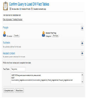
As it can be seen in Fig. 20, the fact table as defined in Fig. 16 named FACT_EVENTS (events) will be loaded with data corresponding to the dimension tables: DM-TIME (date), DM-ACCOMM ( accommodationId), DM-TRANSPORT (serviceId), DM-LOCATION (city), as defined by the mappings with the Integrated Schema. Finally the data for the DW will be loaded into the defined tables and will be ready to be used for exploitation.
4.2 "Transport" domain from the United Kingdom
The datasets we selected for this case study correspond to open data published in United Kingdom [20], and belong to the domain of Transport, in particular accidents and road safety data. They are about the circumstances of personal injury road accidents, the types of vehicles involved and the consequential casualties. The main dataset used is published annually by the Ministerial Department for Transport and contains data about accidents, vehicles, casualties and locations [21]. The other dataset, which complements the former one, is published by the Office for National Statistics [22]and contains a classification for locations in urban and rural areas. We generate a WW where accidents can be analyzed considering the dimensions of vehicles, casualties, locations and date, with different data aggregating criteria. As data is grouped, the analysis indicators are the quantity of vehicles and the quantity of casualties involved in the considered accidents. Fig. 21 presents the conceptual multidimensional model for this analysis, following the model of [16].
Figure 21: Conceptual multidimensional model for Accidents fact
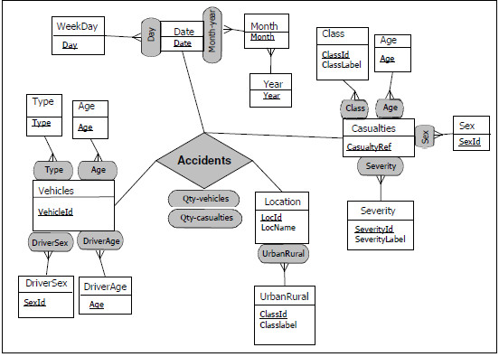
The dimensions in this WW are:
(i) Vehicles, with four different hierarchies: Type, Age, DriverSex and Driver Age, each one containing one level. In this case Age refers to the age of the vehicle.
(ii) Casualties, with five different hierarchies: Class, Age, Sex, Type and Severity, each one containing one level. In this dimension Class refers to the role of the victim (pedestrian, driver or passenger).
(iii) Location, with one hierarchy: Urban-Rural, containing one level.
(iv) Date, with two hierarchies: Month-year and Day. Month-year is a two–levels hierarchy and Day has only one level.
The DW measures are Qty-vehicles and Qty-casualties.
Fig. 22 presents the logical schema of the target DW. Note that the attributes Qty-vehicles and Qty-casualties are not present in the logical schema because they are calculated during the analysis (when the DW is queried by the data cubes manager), counting vehicles or casualties when data is aggregated. This was different in the previous case study, where the measure attributes were included in the logical schema because they could not be calculated from the dimensions data. In the DW-Locations table, attribute id corresponds to the location identification, area-label to the location name, ru-code to the code indicating if it is an urban or rural area, and ru-label to the corresponding label (“urban” or “rural”).
Figure 22: Logical DW schema
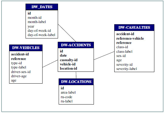
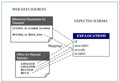
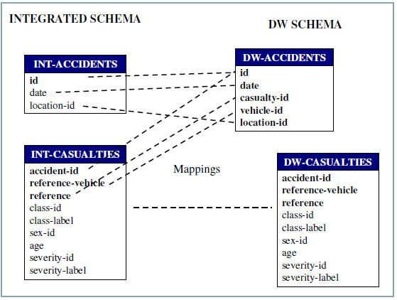
Fig. 23 shows how the expected schema Exp-Locations is configured to be loaded from two different web sources: the Ministerial Department for Transport (S1) and the Office for National Statistics (S2). The attributes id and ru-code are mapped to both sources, while the attributes area-label and ru-label are mapped only to the S2 source. In this way, S2 complements the data obtained from S1, which is the source that corresponds to the accidents data. Data that comes from both sources need to be integrated at the WW feeding phase.
Figure 23: Mappings between expected schema and web sources
Integrated schema attributes of table Int-Casualties are mapped to expected schema attributes as shown in Fig. 24. In this case the attributes corresponding to severity information are mapped to two expected schemas: Exp-Casualties and Exp-Severities. This allows the loading of the label, from table Exp-Severities, corresponding to the severity-id attribute, since this data item is not present in Exp-Casualties table. At the feeding phase, Exp-Casualties will be joined to Exp-Severities through their respective attributes severity-id and id, so that the attributes severity-id and severity-label in table Int-Casualties are correctly loaded.
Figure 24: Mappings between expected and integrated schema
After that, mapping between Integrated schema and DW schema must be performed. Fig. 25 shows the mappings for DW tables DW-Accidents and DW-Casualties. Note that DW-Accidents attributes are mapped to two tables from the Integrated schema, while DW-Casualties is entirely mapped to Int-Casualties table (in the figure these mappings are shown with only one line for clarity).
Figure 25: Mappings between integrated and DW schema
A.Execution of the WW Configuration process
As in the previous example of application, we start a new instance of the configuration process to define all the data to be registered in the configuration database, which will be further read by the feeding process in order to actually load the DW. We will show other screens that were not presented in the previous case study, starting with the option to create a new web source when we do not find the one we want in the already existing ones. In Fig. 26(a) this option is presented, showing the information that has to be provided in order to register a new web source. Fig. 26(b) shows the mapping between the expected schemas defined (the creation is as shown in the previous case study) and the web sources we have just created.
Figure 26: (a) Creating new web sources for the domain "Transport", (b) mapping expected schemas and web sources
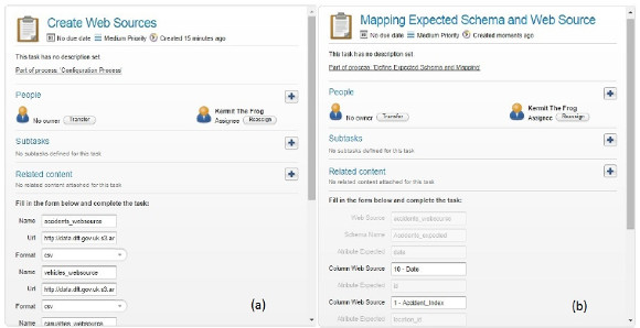
As it can be seen in Fig. 26(a), for each web source you want to register, the user need to provide the name of the web source, the URL where the data is located and the format in which the data is published, to be able to extract it when feeding the DW. In Fig. 26(b) the mappings between attributes from the expected schemas to the corresponding web sources are shown. Note that the attributes shown in grey are read only and that is how we iterate in all tables defined in the expected schemas, until each attribute of the expected tables has its correspondent attribute from a selected web source. This is mandatory of course, to be able to load the data from the web sources into the corresponding expected schemas.
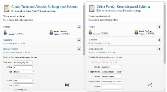
After that the integrated schema is defined in the same way as the expected schema, adding the relations between the tables it contains by defining primary keys of each table and foreing keys to relate them, and also which attributes will be involved in the join between tables that will be performed to load the DW tables. After that the mapping between the integrated schema and the expected schemas is defined, in the same way as before, selecting each attribute of each table of the integrated schema and defining its correspondence with an attribute from an expected schema. In Fig. 27(a) the definition of an integrated schema is shown and (b) the identification of foreign keys among the defined tables and attributes.
Figure 27: (a) Defining the Integrated schema (b) Defining Foreign keys between its tables
After that, the DW schema is defined selecting which is the fact table and which are the dimensions tables, and defining their attributes, primary keys, foreign keys and joins in the same way as it is done for the integrated schema. Finally the mappings between the DW schema tables and attributes and the Integrated schema tables and attributes are defined, in the same way as shown in the previous case study, so we will not repeat it here.
B.Execution of the WW Feeding process
The execution of the feeding process is performed mostly automatically, being only the first activity and the last one of type user task, in the first case to select the configuration to run, and in the second to confirm the query to construct the DW. As the screens are very similar, and we have already presented one that shows the confirmation of the query to load the DW we will not repeat it in this section.
5. Related Work
Different proposals for WW platforms can be found in the literature, focusing on WW development strategies. For example, the project presented in [23][24] has the goal of designing and implementing a WW that materializes and manages useful information from the Web. The authors focus on a Web data model and algebra for web information access, manipulation and visualization, as well as a metadata representation model. Besides, in [25] the author presents a framework for warehousing selected Web content, using a partially materialized approach and an extended ontology to achieve data integration, and in [26] a wrapper - mediator architecture is proposed in order to minimize the impact of Web sources changes on the DW schema. Meanwhile, in [27] the authors pay attention to WWs whose source data are represented through XML. Their proposal focuses on the multidimensional design, deducing the DW schema from the XML structure. Other works also focus on XML DW, solving the problem of processing and facilitating the queries of this kind of semi-structured data [28][29].
Regarding the conceptual definition of business process models to support the construction of DW and/or WW, most related work we have found only focuses in the ETL phase of the construction of a DW and it mainly uses BPMN for design purposes, not to automating the process. For example, in [30][31][32][33] BPMN is used for conceptual modeling of ETL Processes. On the other hand, in [34] the authors propose a framework for all the stages of DW design, based on MDA (Model Driven Architecture), which allows representing the requirements and the components of the DW system with platform independent models (using UML) and then automatically transforming them to platform dependent models. This paper only showed the application of this approach to DW schema design. Later, in [35] a model-driven framework for ETL process development is presented. The framework allows modeling ETL processes in a platform independent way, using a meta-model named BPMN4ETL, and generating vendor specific code from these models. Finally, in [36] the authors propose a layered methodology for designing ETL processes, where the conceptual layer is modeled through BPMN. This model acts as a link between business intelligence and the operational processes of the enterprise. The conceptual model is then translated to the logical model, and then to the physical model. The conceptual and logical models are serialized through XML and the physical model is generated for an ETL engine.
Compared to those, our proposal also supports the ETL phase via a feeding process, including a previous configuration phase in which a configuration process is defined for the user to be able to input data to be used for the actual load of the DW. What is more, the BPMN 2.0 notation is not only used for modeling the configuration and feeding BPs, but also as basis for executing these processes in the open source BPMS Activiti. The provision of automated support to guide the building process of a WW in the way we do, is to the best of our knowledge, not proposed in the literature.
6. Conclusions and Future Work
We have presented the modeling, definitions and data needed to support the process of building flexible WW. Our complete approach is based on the definition of two phases with corresponding BPs: a Configuration phase with a configuration BP which aims to provide support for the user to define and input the data needed to build the WW, and a Feeding BP that in a second phase, using the configuration data, actually generates the WW. We have focused on the configuration BP presenting the model specified in BPMN 2.0, and the executing model also in BPMN 2.0 implemented in the open source BPMS Activiti. We have validated our approach with an application example using open government data from Uruguay and UK, using different languages and from different domains to show its usefulness. Our proof of concept implementation of the configuration BP, although conceptually completed, presents some limitations. For example, we had not yet dealt with modifying already registered data, it could be said we are assuming an ideal user who defines everything correctly the first time. We plan to add more loops allowing the modification of the definitions regarding the schemas and mappings, so to be able to correct or delete things until the user is ok with the definitions. In a similar way, the Feeding process we have implemented was only to validate the configuration data we are registering, and needs more work.
The automated support for building flexible WW we propose will provide organizations with many benefits, including: (i) bridging the gap between the involved roles (Domain Experts and IT professionals) as they can talk about the BP model and understand the different tasks that have to be carried out, (ii) provide easier to use definitions and guides, as in the execution the process engine presents the tasks to be performed accordingly to the control flow defined in the process, (iii) provide automated execution as much as possible, whenever something can be performed automatically based on data retrieved from the user, it will be automated, (iv) provide data about the definitions taken by the user i.e. who defined what in what task, along with many other valuable information regarding the execution of the BPs which is automatically registered in the BPMS process engine as BPs are executed. Also, the contributions of our proposal are in two areas: on the one hand, the conceptual models we have specified for the processes, can be used to support the construction of WW in other BPMS platforms and/or technologies, and on the other hand, our proof of concept implementation in the Activiti BPM platform can be taken "as is" to help speeding and automating the construction of WWs for now.
We are currently working on completely defining the Feeding process to be able to resolve and automate as much as possible some of the issues regarding data integration, and adding data quality management to both the Configuration and the Feeding processes, to complete the automated support for building Quality-Aware flexible WW with BPMS.
Acknowledgements
We would like to thank the students who worked in the development of the Configuration BP and its validation, F. Alonso and M. Mendiola, and, P. Barceló and D. Pérez who are working now with the extension.
References
[1] Open Government Data http://opengovernmentdata.org/ Last accessed Nov. 2015
[2] Marotta A., González L., Ruggia R., "A Quality Aware Service-oriented Web Warehouse Platform". In Proceedings of Business intelligencE and the WEB (BEWEB’12), EDBT, Berlín, Germany, 2012. DOI: 10.1145/2320765.2320783
[3] Weske M., Business Process Management: Concepts, Languages, Architectures, Springer, 2007.
[4] van der Aalst W.M.P.,ter Hofstede A., Weske M., "Business Process Management: A Survey", In Proceedings Int. Conference on Business Process Management (BPM’03), Eindhoven, The Netherlands, 2003. DOI: 10.1007/3-540-44895-0_1
[5] Smith H., Fingar P., Business Process Management:The third wave, Meghan-Kieffer, 2003.
[6] BPMN 2.0, OMG, http://www.omg.org/spec/BPMN/2.0/ Last accessed Nov. 2015
[7] Delgado, A., Ruiz, F., García-Rodríguez de Guzmán, I., Piattini, M. "Application of SOC and MDD paradigms to Business Processes: a systematic review". In Procs 5th Int. Conference on Software and Data Technologies (ICSOFT’10), Athens, Greece, 2010. (DOI 10.1007/978-3-642-29578-2_6 extended version)
[8] Activiti BPMS http://activiti.org/ Last accessed Nov. 2015
[9] Delgado A., Marotta A., González L., "Towards the construction of quality-aware Web Warehouses with BPMN 2.0 Business Processes". In Proceedings IEEE 8th Int. Conference on Research Challenges in Information Science (RCIS‘14), Marrakech, Morocco, 2014. DOI: 10.1109/RCIS.2014.6861041
[10] Delgado A., Marotta A, “Automating the process of building flexible Web Warehouses with BPM Systems” , in Proceedings IEEE XLI Latin American Computing Conference (CLEI ‘15), Arequipa, Peru, 2015. DOI: 10.1109/CLEI.2015.7360005
[11] Dumas M., van der Aalst W.M.P., ter Hofstede A., Process-Aware Information Systems: Bridging People and Software Through Process Technology, ISBN: 978-0-471-66306-5, Wiley&Sons Inc., 2005
[12] XPDL, WfMC, http://www.wfmc.org/xpdl.html Last accessed Nov. 2015
[13] WS-BPEL, OASIS, http://docs.oasis-open.org/wsbpel/2.0/ Last accessed Nov. 2015
[14] Mendling J., Reijers H. A., van der Aalst W.M.P., “Seven process modeling guidelines (7PMG)”, Information and Software Technology, Vol. 52, No.2, 2010 DOI: 10.1016/j.infsof.2009.08.004
[15] van der Aalst, W., ter Hofstede, A., Kiepuszewski, B., Barros, A. "Workflow patterns". Distributed & Parallel Databases, Vol. 14, No.3, 2003 DOI: 10.1023/A:1022883727209
[16] Malinowski E., Zimányi E., Advanced data warehouse design: from conventional to spatial and temporal applications. Springer Science & Business Media, 2008.
[17] Ministerio de Turismo y Deporte. http://apps.mintur.gub.uy/datos Abiertos Last accessed May 2015
[18] Dirección Nacional de Transporte. http://catalogodatos.gub.uy/dataset/aa2405be-6dde-4482-8f5f-563817154282/resource/e62a3ef8-4e00-458b-bcbe-4b293ce0ebba/download/HorariosOmnibusVerano2015.zip Last accessed May 2015
[19] Intendencia de Durazno. http://www.durazno.gub.uy/portal/datos-abiertos/3418-datos-abiertos-de-la-intendencia-de-durazno397 Last accessed May 2015
[20] https://data.gov.uk, Last accessed Nov. 2015
[21] http://data.dft.gov.uk.s3.amazonaws.com/road-accidents-safety-data/Stats19, 2005-2014.zip, Last accessed Nov. 2015
[22] https://geoportal.statistics.gov.uk/Docs/Products/Rural-urban_classification_(2011)_of_lower_layer_super_output_areas_(2011)_E+W.zip,Last accessed Nov. 2015
[23] Bhowmick, S. S., Madria, S. K. & Ng, W. K., Web data management: a warehouse approach. Springer, 2004.
[24] Bhowmick, S.S., Madria, S. K. & Ng, W. K., Representation of Web Data in A Web Warehouse. Computer Journal, Vol. 46, No.3, pp. 229-262, 2003, DOI: 10.1093/comjnl/46.3.229
[25] Zhu, Y. “A Framework for Warehousing the Web Contents”, In Proceedings 5th International Computer Science Conference (ICSC’99), Hong Kong, China, 1999. DOI 10.1007/978-3-540-46652-9_9
[26] Marotta, A., Motz, R. & Ruggia, R. “Managing source schema evolution in web warehouse”, Journal of the Brazilian Computer Society, Vol. 8, No.2, pp. 20-31, 2002
[27] Vrdoljak, B., Banek, M., Rizzi, S., “Designing Web Warehouses from XML Schemas” in Proceedings 5th International Conference Data Warehousing and Knowledge Discovery (DaWaK ‘03), Prague, Czech Republic, 2003. DOI: 10.1007/978-3-540-45228-7_10
[28] Zhang, J., Ling, T. W., Bruckner, R. M., Tjoa, A. M., “Building XML Data Warehouse Based on Frequent Patterns in User Queries” in Proceedings 5th International Conference Data Warehousing and Knowledge Discovery (DaWaK ‘03), Prague, Czech Republic, 2003. DOI 10.1007/978-3-540-45228-7_11
[29] Rusu, L. I., Rahayu, J. W., Taniar, D.,“A Methodology for Building XML Data Warehouses”, International Journal of Data Warehousing and Mining (IJDWM), Vol. 1, No. 2, pp. 23–48, 2005.
[30] Akkaoui Z. E., Mazón J.-N., Vaisman A., Zimányi E., “BPMN-Based Conceptual Modeling of ETL Processes” in Proceedings 14th International Conference Data Warehousing and Knowledge Discovery (DaWaK ’12), Vienna, Austria, 2012. DOI 10.1007/978-3-642-32584-7_1
[31] Oliveira B., Belo O., “BPMN Patterns for ETL Conceptual Modelling and Validation” in Foundations of Intelligent Systems: Proceedings 20th International Symposium (ISMIS ’12), Macau, China, 2012. DOI 10.1007/978-3-642-34624-8_50
[32] Berkani N., Bellatreche L., Khouri S., “Towards a conceptualization of ETL and physical storage of semantic data warehouses as a service”, Cluster Computing, Vol. 16, No. 4, pp. 915–931, 2013.
[33] Vasileios T., Abelló A., Lehner W., "Quality measures for ETL processes", Proceedings 16th International Conference Data Warehousing and Knowledge Discovery (DaWaK'14), Munich, Germany, 2014. DOI 10.1007/978-3-319-10160-6_2
[34] Mazón, J.-N. , Trujillo, J. , Serrano, M. A., Piattini, M., “Applying MDA to the development of data warehouses” in Proceedings ACM 8th International Workshop on Data Warehousing and OLAP (DOLAP’05), Bremen, Germany, pp. 57–66, 2005. DOI 10.1145/1097002.1097012
[35] Akkaoui Z. El, Zimànyi E., Mazón J.-N., Trujillo J., “A Model-driven Framework for ETL Process Development” in Proceedings of the ACM 14th International Workshop on Data Warehousing and OLAP (DOLAP’11), New York, USA, pp. 45–52, 2011. DOI 10.1145/2064676.2064685
[36] Wilkinson, K., Simitsis, A., Castellanos, M., Dayal, U., “Leveraging Business Process Models for ETL Design”, In Proceedings 29th International Conference on Conceptual Modeling (ER’10), Vancouver, Canada, pp. 15-30, 2010. DOI 10.1007/978-3-642-16373-9_2

