


Servicios Personalizados
Revista

Articulo
 Inglés (pdf)
 Articulo en XML
 Referencias del artículo
Links relacionados
Compartir

 Permalink
CLEI Electronic Journal
versión On-line ISSN 0717-5000
CLEIej vol.18 no.2 Montevideo ago. 2015
Towards an automatic model transformation mechanism from UML state machines to DEVS models
Abstract
The development of complex event-driven systems requires studies and analysis prior to deployment with the goal of detecting unwanted behavior. UML is a language widely used by the software engineering community for modeling these systems through state machines, among other mechanisms. Currently, these models do not have appropriate execution and simulation tools to analyze the real behavior of systems. Existing tools do not provide appropriate libraries (sampling from a probability distribution, plotting, etc.) both to build and to analyze models. Modeling and simulation for design and prototyping of systems are widely used techniques to predict, investigate and compare the performance of systems. In particular, the Discrete Event System Specification (DEVS) formalism separates the modeling and simulation; there are several tools available on the market that run and collect information from DEVS models. This paper proposes a model transformation mechanism from UML state machines to DEVS models in the Model-Driven Development (MDD) context, through the declarative QVT Relations language, in order to perform simulations using tools, such as PowerDEVS. A mechanism to validate the transformation is proposed. Moreover, examples of application to analyze the behavior of an automatic banking machine and a control system of an elevator are presented.
Spanish Abstract:
El desarrollo de complejos sistemas guiados por modelos requiere de estudios y análisis previos a la implementación, con el objetivo de detectar comportamientos no deseados. UML es un lenguaje ampliamente usado por la comunidad de ingeniería de software para modelar estos sistemas a través de las máquinas de estados, entre otros mecanismos. En la actualidad, estos modelos no disponen de adecuadas herramientas de simulación y ejecución para analizar el comportamiento real de los sistemas. Las herramientas existentes no proveen librerías apropiadas (para el muestreo de distribuciones de probabilidad, ploteo, etc.) para construir y analizar modelos. El modelado y la simulación para el diseño y prototipado de sistemas son técnicas ampliamente usadas para predecir, investigar y comparar la performance de los sistemas. En particular, el formalismo Especificación de Sistemas de Eventos Discretos (Discrete Event System Specification - DEVS) separa el modelado de la simulación. Existen varias herramientas disponibles en el mercado que ejecutan y recopilan información de modelos DEVS. Este artículo propone un mecanismo de transformación de modelos de máquinas de estados UML a modelos DEVS en el contexto del desarrollo dirigido por modelos (Model-Driven Development - MDD) mediante el lenguaje declarativo QVT-Relations, a fin de realizar simulaciones utilizando herramientas tales como PowerDevs. Asimismo, se describe una propuesta para validar la transformación desarrollada. Finalmente, se presentan dos ejemplos de aplicación. El primero analiza el comportamiento de un cajero automático de un banco y el segundo analiza un sistema de control de ascensores.
Keywords: Statecharts, DEVS, UML, MDA, QVT Relations.
Spanish Keywords: Máquinas de Estados, DEVS, UML, MDA, QVT Relations.
Submitted: 2014-11-11. Revised: 2015-04-07. Accepted: 2015-07-12.
1 Introduction
Model-Driven Development (MDD) [1, 2, 3] is a methodology that advocates the use of models as the primary artifacts that drive the development of software, in order to increase productivity, quality and reduce costs [4, 5]. One of its main objectives is to organize abstraction levels and development methodologies, promoting the use of models as the main artifacs to be constructed and maintained. A model consist of a set of elements that provide a synthetic and asbtract description of a system, specific or hypothetical. Thus, the development process becomes a refinement process and transformation between models, increasingly generating lower-level abstraction models until, in the last step, specific platform code is generated. There is a growing interest in this field. In particular, the Model-Driven Architecture (MDA) [6] is the approach defined by the Object Managment Group (OMG) [7].
For the MDD, the Unified Modeling Language (UML) [7, 8] has become the standard for modeling the different aspects of software systems, both in the academic environment and industrial developments. UML follows the Object Oriented paradigm and allows the description of both static and dyanimc aspects of software systems. More than a language, it is a set of languages, mostly graphic notations, supported by a significant number of proprietary and open source tools [9]. While UML is one of the preferred means of communication between modeling experts, due to powerful grapical representation, this capacity is bounded in term of model execution, that is, the execution of a simulation.
In the simulation area, the Discrete Event System Specification (DEVS) [10] is a modular and hierarchical formalism modeling and analyzing systems of various types; in particular, discrete event systems, systems of differential equations (continuous systems), and hybrid systems (continuous and discrete) [11, 12]. DEVS provides a theoretical basis for a system to run models using the DEVS simulation protocol [10, 13, 14]. The DEVS models are hierarchical in nature and consist of atomic models and coupled models in order to build designs at different levels of asbtraction.
There is currently a major need of simulation tools for dynamic UML models to analyze the actual behavior of complex systems. Moreover, it is recommended to apply modeling and simulation techniques in early stages of software development, as these help to detect inconspicuous problems before deployment. UML is powerful in terms of its graphical representation, but weak regarding the execution of their dynamic models. In the software engineering community, state machines are one of the most used UML modeling languages [9, 15]. The present work aims to enhance the simulation of these using the DEVS formalism. Currently, DEVS is widely used by engineers within the academic world, who understand the modeling of discrete event systems and are capable of translating system requirements to DEVS model code.
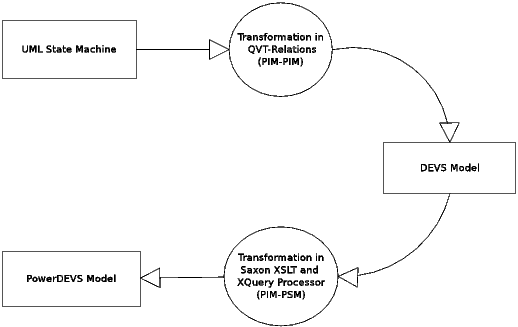
The main objective of this work is the proposal of a mechanism to execute and analyze UML state machines through DEVS, a modeling and simulation formalism (M&S). A formal relationship is defined between elements of the state machines (State Charts - SCs), proposed by Harel [16], and the elements of the DEVS formalism [10]. Furthermore, a DEVS representation (metamodel) is defined and a mapping from UML statecharts to DEVS models is presented, through transformation rules implemented in QVT Relations language (QVT-R) [17]. Finally, the implementation of a DEVS model is built and can then be imported by the PowerDEVS Simulation Tool [18] for the execution and analysis of the model. Even though the development and analysis of simulations (on models obtained from the transformation) are not the focus of this work, we include examples of analysis of applications. Figure 1 shows the described process.
Even though the transformation of UML models for simulation purposes is not a new idea, and there also exist other similar approaches that can be used as reference, this paper provides a sound process for achieving this objective, from both the conceptual perspective and the technical implementation perspective. This is the main contribution of this work.
The rest of the paper is organized as follows. In Section 2 we describe the motivations that give rise to the current proposal, along with other related works that are directly linked to this one. Section 3 introduces the theoretical components that form the basis of the main issues, such as MDA, the SC’s, and the DEVS formalism. In Section 4 we present the formal transformation process of SC’s to DEVS models. Then, in Section 5 we define, first, the relations in QVT-R that implement the process, and then the C++ code generation to be imported by PowerDEVS. Section 6 describes a proposal to validate the transformation. In Section 7 includes two application examples: the analysis of the behavior of an automatic banking machine and a control system of an elevator. Finally, in Section 8 detailed conclusions and future work discussions are presented.
The full development is available at https://www.dropbox.com/sh/4e0zorfyvgdmdg3/dnfWO_ija9.
A preliminary version of this paper appeared in XL CLEI [19].
2 Motivation and Related Work
Mapping UML components to DEVS models (and vice versa) is not a new idea, nor an isolated initiative. There are many research projects that aim to integrate developments in modeling and simulation, generating different methodologies, processes and specific frameworks. However, our proposal differs from previous works on issues that we discuss in this section.
There are different tools that support UML (UML Computer Aided Software Engineering - UML CASE) providing simulation capabilities, such as IBM Rational Rose [20, 21] and Poseidon [22]. These tools have proprietary simulation engines which are not extensible and can not be tailored to meet specific requirements. For the current proposal a specific simulation engine is required to support simulation processes in detail (time event management, probability distributions, etc.), such as PowerDevs.
For the representation of DEVS models there are different approaches. One of such approaches is the Structure Entity Modeler Scalable with Complexity Measures (SESM/CM) [23] which is adequate for: developing component-based hierarchical models, modeling behavioral aspects of atomic models, providing structural specifications, and storing the models using XML. However, this approach is closer to the simulation experts than domain experts and it needs further development to represent atomic models using XML.
In [24] and [25] another metamodel is defined to represent DEVS systems through XML. In both cases, JavaML [26] is used to describe the behavior of an atomic model. This solution is suitable for transforming platform specific models to platform independent models, but it does not provide a graphical solution for modeling such systems. One of the goals of our research project is to incorporate in the future a tool for viewing and editing models. Another tool that is available is ATOM3 [27] which is a good solution since it has a layer of metamodeling that allows describing domain specific modeling languages, and a layer that supports construction, modification and transformation of domain models.
In the field of modeling and simulation based on UML, several authors have approached the subject from different perspectives. Choi [28] uses UML sequence diagrams to define the behavior of a system. In [29] eight steps to build DEVS models using UML are introduced, but in this case many human decisions are needed to transform the model.
In [30], Zinoviev presents a formal mapping from DEVS to UML. In this technique, input and output ports are mapped to UML events. Not continuous DEVS state variables are mapped to UML states and those that are continuous are mapped to attributes of an UML state. The mapping presented is elegant, yet their representation in UML does not tend to provide a unified representation for the modeling formalism.
Huang and Sarjoughian define in [31] a mapping for coupled models in UML-RT structure diagrams [32, 33], but the use of UML profiles for planning, performance and time specification (OMG2005) is unnecessary for mapping DEVS to UML. They conclude that UML-RT is not suitable for a simulation environment, and argue that the software design and simulation are inherently different.
In [34] an informal mapping from DEVS to a STATEMATE statechart is introduced. Shulz indicates that DEVS has greater expressive power than the statechart [35], and that any DEVS model can be represented by a StateMate activity diagram, together with an appropiate indentifier convention for events.
In the MDA context, Tolk and Muguira [36] show how complementary ideas and methods of High Level Architecture (HLA) and DEVS can be integrated into a well-defined M&S application domain, within the MDS framework. HLA has a distributed simulation architecture, independent of the computing platform. It provides an interface in which each simulation engine must conform to participate in a distributed simulation exercise. While it is widely used in the defense industry, its adoption in commercial industry has been restricted. The HLA interface specification does not include a network protocol for Run-Time Infrastructure (RTI). It is up to the developers of an RTI to create a specification. Due to this, interoperability between RTI products and often, RTI versions, should not be assumed, therefore, this limits their use in commercial industry.
Transformations between UML and DEVS models are presented in [37] and [38]. In [37], the authors transform sequence diagrams to Finite and Deterministic DEVS to verify by means of space state exploration and to validate a set of traces by means of a simulation. The extension of the modeling language based on DEVS (E-DEVSML) proposed in [38] can help modelers to simulate systematically the systems. Also, an approach to make UML diagrams executable through an automated model transformation process using E-DEVSM is described. However, it does not specify the types of UML diagrams that are transformed and presents a proposal based on scarce bibliography. Neither [37] or [38] analyze the validation of the transformation or discuss possible mechanisms.
In [39], the authors present a new extension to the DEVS formalism, called Rational Time-Advance DEVS (RTA-DEVS) which can be fomally checked with standard model-checking algorithms and tools. This is done by means of a procedure that creates Timed Automata models that are behaviorally equivalent to the original RTA-DEVS models via a transformation models. This paper also presents a validation mechanism of transformation using the technique known as Correctness-by-Construction.
In [40], Mittal and Risco-Martin present eUDEVS (Executable UML with DEVS Theory of Modeling and Simulation) where the authors analyze not only the specification of the structure and the behavior of DEVS models in UML, but also a method for modeling general purpose DEVS models, which supports the specification, analysis, design, verification and validation of a wide variety of systems based on DEVS. In [40] an M&S methodology consisting of three steps is proposed. First, the static structure of the UML state machine is synthesized and its corresponding representation in State Chart XML (SCXML) [41] is generated. Second, the SCXML file is converted to a DEVS finite and deterministic state machine model (Finte Deterministic DEVS - FD-DEVS), defined by Mittal in [42], which specifies its behavior. At this stage the model is totally platform independent. Finally, from the XML FD-DEVS, a simulation model is generated using a series of XML-based transformations, to be executed later by the DEVSJAVA [43] simulation engine. The proposed method is interesting and ambitious, but the employment of XSL transformations (eXtensible Stylesheet Language Transformations - XSLT) makes it unclear. Additionally, the work is based on a representation of the SCXML state machine defined by the World Wide Web Consortium (W3C), which does not consider all elements of UML state machines. SCXML is a general-purpose event-based state machine language that can be used in many ways and is currently a working draft specification. Also, it provides a generic state-machine based execution environment based on Harel state tables, Commons SCXML. Commons SCXML is an implementation that creates and maintains a Java SCXML engine capable of executing a state machine defined using a SCXML document, however, it does not provide libraries for analysis of the models.
This work differs from the above, and especially from [40], in the following aspects:
- A proposal in the context of the MDA is made;
- A formal mapping between the SC’s, defined by Harel, and DEVS models is performed;
- A QVT-R transformation, model-to-model (M2M), implementing the mapping from UML state machines to DEVS models is defined. It employes a declarative language standardized by the OMG instead of using imperative languages or XML transformation tools. The instrumentation of transformation rules through XML definitions leads, in general, to unclear and difficult developments. XSL transformations are very different from a programming language since they are based on the use of templates which often are difficult to maintain when they become large. In contrast, transformation languages such as QVT and ATL have similar styles to programming languages. In particular, QVT-R follows the style of the logical-relational paradigm. This feature allows us to define transformations as declarative, modular, easier to extend and modify specifications.
- A C++ code of DEVS models is generated to be imported by the PowerDEVS (open source) simulation tool.
- Mechanisms to validate transformations are discussed, while this is not done in [40].
- Our proposal focuses on discrete dynamical systems, where time constraints occur in many places and drive the evolution of these systems. For example, elevator systems and assembly machines.
Even though the transformation of UML models for simulation purposes is not a new idea, and there also exist other similar approaches that can be used as reference, we propose a model transformation mechanism from UML SC’s to DEVS models in the MDD context, through the declarative QVT-R language, in order to perform simulations using tools, such as PowerDEVS. Further research will develop a unified tool that contains a specific modeling environment that allows the representation of systems with UML elements considered in this work, along with the transformation to DEVS models. We also propose to integrate PowerDEVS for the implementation and analysis of the models.
3 Preliminary Notions
3.1 Model-Driven Architecture (MDA)
MDA is an OMG initiative that proposes a set of standards which specify interoperable technologies to implement the principles of MDD, incorporating automated transformations. MDA defines a process of software construction based on the production and processing of models. The principles on which MDA is based are: abstraction, automation and standardization. The MDA central process consist in model transformation. The main underlying idea is to use models, so that the properties and characteristics of the systems remain contained in an abstract model, independent of the changes in technology. MDA provides a set of guidelines or standards expressed as models and establishes four levels of abstraction: Computation Independent Model (CIM), Platform Independent Model (PIM), Platform Specific Model (PSM), and the final application. The CIM models describe the environment in which the system is used, without direct reference to its implementation. The PIM models describe the functionality and structure of an information system without considering technological details of the platform on which the system is implemented. The PSM models describe the specific platform where the system is executed. MDA proposes the following development process: from requirements we get a PIM, then this model is transformed with the help of one or more tools in PSM, and finally each PSM is transformed into code. Therefore, MDA incorporates the idea of models transformation (CIM to PIM, PIM to PSM, PSM to code), making use of tools for the automation of these activities. Figure 2 shows the process and the roles defined by MDA.
The principle of abstraction used by MDA focuses its attention on the problem domain rather than on the technology. Different models aim at the definition of a semantic that separates relevant aspects of the problem from those related to the technology. Regarding automation, MDA favors the emergence of new CASE tools with specific functionalities for the exchange of models, consistency verification, processing and handling of meta models, among others.
Mapping and Model Transformation
A set of mappings between models from different abstraction levels are established in Figure 2. These mappings can also be defined between models belonging to the same level. Below are some of the possible transformations:
- Mapping PIM to PIM. It is applied in order to optimize them for the duration of the development process. This mapping does not require any information on the implementation platform.
- Mapping PIM to PSM. It is applied in cases where it has a PIM resulting from a series of refinements of PIM to PIM. This mapping will be implemented in a dependent architecture of a specific platform.
- Mapping from PSM to PSM. It is applied during the encoding and component development. This mapping is linked to the refinement of PSM own models.
- Mapping from PSM to PIM. This transformation may be required to generate abstract models from existing implementations. It can be used in order to extract into generic models, desirable properties of a system.
- Mapping from PSM to code. Enables the generation of specific source code to a particular platform from a PSM.
The languages most commonly used to describe model-to-model transformations are QVT and ATL (Atlas Transformation Language) [44]. In the present work we opted for QVT-R (QVT-Relations) for its simplicity and clarity to define relationships between elements of the source and target metamodels.
Query/View/Transformation (QVT) The OMG defined the QVT standard [17] to work with software models. QVT consists of three parts: query, view and transformation. In particular, a transformation metamodel describes relationships between a source metamodel S, and a target metamodel T, specified in MOF [45]. The QVT specification 1.1 has a declarative/imperative hybrid nature. In this work the Relations declarative language is employed. The tool used for the definition of the transformations is called MediniQVT [46]. This tool implements the OMG QVT-R specification into a powerful engine QVT. Its interface is based on Eclipse, and use Eclipse Modeling Framework (EMF) [47] for representing models. MediniQVT requires that metamodels (and models) be written in a simplified version of the MOF standard, called Ecore [48], which is defined in the EMF. An Ecore metamodel is represented in XML; however has an EMF Ecore models graphic editor which facilitates the creation thereof.
Ecore and Ecplispe Modeling Framework Characteristics The metamodels and EMF models used are represented by XML documents; EMF has a graphical editor which facilitates the creation of Ecore models. There are tools that automatically treat these metamodels and models, including the Eclipse plug-in to transform these models, with the definition of QVT transformations. The features and elements of the modeling language Ecore are: the unifying element (root) is the package EPackage, which physically contains its elements (containment specification) and, in turn, these may be contained in other packages. There is a factory (EFactory) per package that allows the creation of model elements. Constructs that describe a set of elements (instances) are classifiers (EClassifiers): EClass and eDataType. Ecore specifies the characteristics of the classes (EClass), their structural characteristics (EStructuralFeatures), attributes (EAttributes), operations and relationships (inheritance, reference (EReference)). The EClass have a superclass and is composed of structural features (EStructuralFeatures: EReference and EAttribute). Both EAttributes and EReferences may be provided with multiplicity. The EDataTypes model basic or indivisible data model types, and the EReferences may be contained or be references (pointers). The Operations model the operations of the interface (although implementation is not provided for them). All elements inherit from ENamedElement (nameless) and EModelElement (model element). Moreover, every element of the model can have associated annotations (EAnnotation): name / value pairs for additional specifications; eg, OCL constraints or documentation strings.
3.2 State Machines
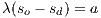
A SC is a visual representation of a finite state automata with hierarchy of states. These machines were introduced by Harel [16] and incorporated into the various versions of UML with some variations. The main feature of the SCs is that their states can be refined, thus defining a hierarchy of states. The decomposition of a state can be sequential or parallel, in the first, a state decomposes into an automaton, while in the second it breaks down into two or more automata running concurrently. Although this hierarchy is allowed, a SC with composite states has its equivalent using only simple statements. In this paper, we will rely on the definition and application of SCs containing only simple statements. There are many algorithms and tools that convert a SC with composite states to an equivalent SC with simple states [16, 49, 50]. Transitions are directed. A transition (t) is formed by its name, origin state, the event that “triggers” it (e), the trigger condition (c), the actions to be executed ([alpha]) and destination state. The graphical notation used is  .
.
3.3 M&S and DEVS
A model is a representation of the construction and working of some system of interest. A model is similar to but simpler than the system it represents. One purpose of a model is to enable the analyst to predict the effect of changes to the system. On the one hand, a model should be a close approximation to the real system and incorporate most of its salient features. On the other hand, it should not be so complex that it is impossible to understand and experiment with it. Generally, a model intended for a simulation study is a mathematical model developed with the help of simulation software. Mathematical model classifications include deterministic (input and output variables are fixed values) or stochastic (at least one of the input or output variables is probabilistic); static (time is not taken into account) or dynamic (time-varying interactions among variables are taken into account). Typically, simulation models are stochastic and dynamic.
Simulation is a descriptive tool, allowing us to experiment with a model instead of the real system. The propose of simulating, generally falls into one of three categories as follows:
- Comparison. A comparison of simulation runs can be used to assess the effect of changing a decision variable. The results of the different runs can then be evaluated in terms of the objetives.
- Prediction. A simulation may be used for predictive proposes to determine the state of the system at some future point in time, subject to assumptions about how it behaves now and how it will continue to behave.
- Investigation. Some simulations are developed to provide an insight into the behavior of the system, rather than to perform detailed experimentation. It is of interest to see how the simulation behaves and reacts to normal and abnormal stimuli.
Simulation is used before an existing system is altered or a new system built, to reduce the chances of failure to meet specifications, to eliminate unforeseen bottlenecks, to prevent under or over-utilization of resources, and to optimize system performance.
During the last decades, the rapid evolution of technology has produced a proliferation of new dynamical systems of great complexity. Examples include computer networks, automated production systems, air traffic control, and general systems of command, control, communications and information. All the activities in these systems are due to the occurrence of asynchronous discrete events, some controlled (such as pressing a key) and some not (like spontaneous equipment failure). This feature is what leads to define the term: Discrete Event Systems (Discrete-Event Systems - DES) [51]. Among the most popular formalisms for representation of DES are Petri Nets, the SC, Grafcet, Event Graphs, and many generalizations and particularizations of them.
With the motivation of problem-oriented modeling and simulation of DES, in the decade of the ’70 Bernard Zeigler proposed a theoretical framework and a methodology for M&S systems. It is here that arises DEVS [10], a formalism for modeling with a solid semantic, based on a theoretical system basis. This formalism, sometimes pointed as universal, allows to describe dynamic discrete event systems. Its universality means that any formalism for these systems can be adjusted to DEVS. Because of its great adaptation for modeling complex systems and the simplicity and efficiency of the implementation of simulations, DEVS is currently one of the most used tools in modeling and simulation by mean of discrete events. In Section 4.2 the details of the formalism are presented.
4 From State Machines to DEVS Models
The main objective of this work is to provide a mechanism that achieves the execution of UML SCs, through a process that transform them to DEVS atomic models, to later be able of carrying simulations on them. To build this process of transformation is necessary to make a review of the elements of each formalisms. Subsequently, a mapping between them through a set of rules that indicate how information from one domain translates to another is defined. These rules are especially needed because although the domain elements of a SC has similar aspects from the DEVS ones, the specification of DEVS elements is more stringent.
4.1 Formal Definition of a SC
The UML SCs are based on the SCs defined by Harel. They are composed by a set of states, transitions and events. Formally, following [52], a SC is defined as a tuple  , where:
 : is a finite (non-empty) set of states.
  : is a finite set of events.
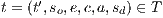
  is a finite set of transitions represented by the tuple
 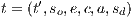 , where:
  is the transition name;
  is the origin state;
  is the trigger event;
  is a trigger condition;
  A is an action to be executed when the transition occurs;
  is the destination state.
 : is a set of actions, where
  represents the “null action” or “skip”.
For convenience, a life time (or residence time) can be associated to a state. These are used to describe a new behavior, that defines for how long the system can remain in a state. When time has elapsed, a special transition must be triggered. This behavior could also be implemented by associating a time event to a transition, which fires when the origin state reaches that time. On one hand, the association of time to each state is formalized, and secondly, a special event  called time event to be used in transitions that are triggered upon reaching the time in his origin state. We refer to these transitions as time transitions. Only one time transition must be defined by each state, and the life time must be not equal to
  .
.
The SC formal definition is extended with the following components:  , where:
 is a set of pairs that associates with each state a value in
  , that represents the life time.
  is the time event.
 - Si
 then there must be a unique time transition
 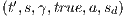 with origin
  .
.
Figure 6 shows an example of a SC. Note that the transitions are triggered when the life time runs out in their origin state (time transition) are drawn simply by associating the life time of their origin state and action output; the event (event time  ) and condition (
 ) are not drawn.
4.2 Definition of DEVS Formalism
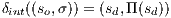
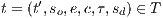
A classic DEVS atomic model is defined as a tuple 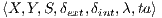 , where:
 is the set of input events (possibly
  ).
).  is the set of output events (possibly
  ).
).  is the set of states (possibly
  ).
). 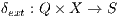 is the external transition function which defines how an input event changes a state of the system, where:
  is the set of total states, and
  theis the elapsed time since the last event.
  is the internal transition function which defines how a state of the system changes internally (when the elapsed time reaches to the lifetime of the state).
  is the output function. This function defines how a state of the system generates an output event (when the elapsed time reaches to the lifetime of the state).
  is the time advance function which is used to determine the lifespan of a state.
A system that is in a state  will remain in it for a
  period of time, unless an input event with value
  occurs, after a time
  lower or equal to
  elapses. In this case, the system will experience an external transition to the state
  . However, if the elapsed time
  is equal to
  without external events have taken place, an internal event will occur leading to an internal transition. This will produce an output event with value
  and a transition to a new state
  . In both cases, the system will remain in the new state, by the time
  determined or until an external event occurs again.
Note that in the definition of DEVS filed, the time advance function supports associating a time  or
or  to a state
  . In the first case, the system may remain
  units of time in
  . Therefore, when
  is reached, an internal transition happen immediately generating an output event and a state change. Such a state is called transitory state. Moreover, when the system reaches s whose associated time is
  , no internal transitions will exist and will remain forever in this state unless an external event occurs. Such a state is called passive.
4.3 Element Mapping
Model transformations are defined as programs that take a model (or more than one) as input and returns another model (or more than one) as output.Consist of a set of rules describing how one or more source model elements are transformed into one or more elements of the target model. Below is formally defined the set of rules that describe how the elements of the source model are transformed into elements of the target model by extracting the necessary information from a SC to build a DEVS atomic model.
Given ME = 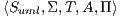 a SC, and MA =
  a DEVS atomic model, the transformation rules are defined as follows:
- 1.
- Rule 1: states from
 and their life time are transformed DEVS states, where:
  . On the other hand, the
  function is defined as:
  .
. - 2.
- Rule 2: an event
 is transformed into a DEVS input event with the same name;
  .
. - 3.
- Rule 3: an action
 is transformed into a DEVS output event with the same name;
  .
. - 4.
- Rule 4: to define the transitions mapping is necessary to distinguish particular cases, as in ME all the information is contained in the tuple that defines the transition, while on a DEVS model it is specified in various elements of the atomic model. This classification is to distinguish transitions according to their trigger (event time and the rest), and according to a certain action or null action attached to it.
- Rule 4.1: a transition
 that is triggered by the occurrence of a time event (
 ), is transformed into an internal transition in MA.
 Given
 :
:  , and
, and 
- Rule 4.2: a transition
 that is triggered by the occurrence of an event
  and contains the null action
  , it is transformed into an external transition in MA.
 Given
 , where
  :
: else
else 
- Rule 4.3: a transition
 that is triggered by the occurrence of an event
  and contains a non-null action
  , produce the following elements in MA.
 Given
 , where
  , and
, and  :
: - (a)
- it is defined an intermediate state
 with life time 0, in order to produce as output of the model MA, the action
  :
:  ;
; - (b)
- an external transition from
 to
to  :
:  ;
; - (c)
- an internal transition from
 to
to  :
:  ;
; - (d)
- an element from the output function that maps
 to the output event (action)
  :
:  .
.
- Rule 4.1: a transition
5 Implementing the Transformation with QVT and Exporting to PowerDEVS
In this section an implementation of the transformation rules from UML statecharts to DEVS atomic models based on the QVT-R language is proposed. Subsequently, the exporting method of the resulting model is described, so that it can be interpreted by PowerDEVS.
A set of QVT relations that implement the rules detailed in Section 4.3 is defined. We make use of the UML 2.4.1 metamodel described in the official website of the OMG [8]. In function of this specification, the UML elements that are used to support the formalism of the SCs defined in 4.1 are described. Later, the DEVS formalism metamodel presented in Section 4.2, is defined in Ecore format.
An execution of rules in QVT receives a model (or instance) of a UML SC satisfies the UML metamodel in Ecore [47], and builds a DEVS atomic model that satisfies the respective metamodel in Ecore format.
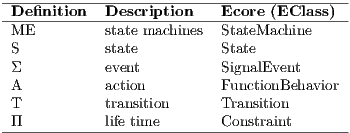
Table 1 reflects briefly which UML elements are used to model the SCs defined in Section 4.1.
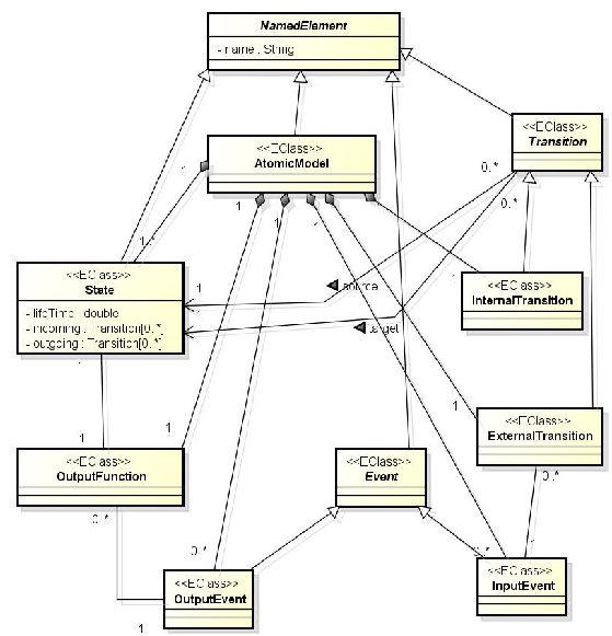
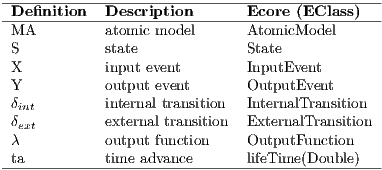
DEVS Metamodel
The DEVS metamodel definition is based on the specification described in Section 4.2 and is built with the MediniQVT tool. Note that each element of the tuple that defines the DEVS models is defined by a metaclass. Figure 3 shows graphically that metamodel. Briefly, Table 2 describes the relationship between the elements from the formal definition of an DEVS atomic model and elements of the Ecore metamodel.
5.1 Transformation Rules in QTV-R
The definition of relationships (rules) in QVT-R implement the rules specified in 4.3. These transformation rules are written declaratively and describe consistent relationships between the set of elements of each model. This consistency can be verified by running the transformation in checkonly mode (read-only), with a satisfactory result if both models are consistent according to the relations. Similarly, it can be executed in enforce mode to modify or build one of the models, so that both satisfy the relations at the end of the execution. In this paper, QVT relationships are built by checking the UML model, and enforcing the DEVS one, thus the elements of first maps to elements of the second.
For space reasons, the relevant parts of the code relationships are shown. In particular, only the construction of states, input events and partly the construction of internal and external transitions from the DEVS atomic model are shown. In https://www.dropbox.com/sh/4e0zorfyvgdmdg3/dnfWO_ija9 it is possible to download the full definition of the rules. Note that a rule defined in Section 4.3 may be implemented by more than one relationship in QVT-R.
The relationship state2state builds the DEVS model states according to the following mapping: the name of the DEVS state corresponds to the name that has in the UML model and its lifetime specified on the UML (Constraint) time constraint.
nameS: String;
checkonly domain smUml s_source :uml::State {
container = regionsource :uml::Region{
stateMachine = sm :uml::StateMachine{} },
stateInvariant = s_stateInvariant :uml::Constraint{
specification = spec :uml::ValueSpecification{} },
name = nameS
};
enforce domain smDevs s_target :devs::State {
atomicModel = am :devs::AtomicModel{},
lifeTime = spec.oclAsType(uml::LiteralDouble).value,
name = nameS
};
when {
statemachine2atomicmodel(sm,am);
}
}
The UML events SignalEvent are mapped to InputEvent elements of the DEVS metamodel. This is defined by the relationship signalEvent2inputEvent.
nameT : String;
checkonly domain smUml s_source :uml::SignalEvent {
name = nameT
};
enforce domain smDevs s_target :devs::InputEvent {
name = nameT
};
}
A UML transition that is triggered by the ocurrence of an external event and contains an action attached to it, creates various elements of the resulting DEVS atomic model, according to the last rule defined in Section 4.3.
top relation transition2mediatorState {
nameT : String;
checkonly domain smUml s_source :uml::Transition {
container = regionsource :uml::Region{
stateMachine = sm :uml::StateMachine{} },
source = ss_uml :uml::State{},
target = st_uml :uml::State{},
trigger = t_uml :uml::Trigger{
event = se_uml :uml::SignalEvent{} },
effect = a_uml :uml::Activity{
classifierBehavior = fb_uml :uml::FunctionBehavior{} },
name = nameT
};
-- Middle Status
enforce domain smDevs s_target_MS :devs::State {
atomicModel = am :devs::AtomicModel{},
lifeTime = 0.0,
name = ss_uml.name + ’-’ + st_uml.name
};
-- External transition
enforce domain smDevs s_target_ET :devs::
ExternalTransition {
atomicModel = am :devs::AtomicModel{},
source = ss_devs :devs::State{},
target = s_target_MS,
inputEvent = ie_devs :devs::InputEvent{},
name = ss_uml.name + ’to’ + s_target_MS.name +’(?’ + t_uml.name+’)’
};
-- Internal Transition
enforce domain smDevs s_target_ITTarget :devs::
InternalTransition {
atomicModel = am :devs::AtomicModel{},
source = s_target_MS,
target = st_devs :devs::State{},
name = s_target_MS.name + ’to’ + st_uml.name
};
-- Output Function
enforce domain smDevs s_target_OF :devs::OutputFunction {
atomicModel = am :devs::AtomicModel{},
state = s_target_MS,
outputEvent = oe_devs :devs::OutputEvent{},
name = s_target_MS.name + ’(!’ + fb_uml.name + ’)’
};
-- Preconditions
when {
state2state(ss_uml,ss_devs);
state2state(st_uml,st_devs);
signalEvent2inputEvent(se_uml, ie_devs);
function2outputEvent(fb_uml,oe_devs);
isUmlExternalTransition(s_source);
statemachine2atomicmodel(sm,am);
}
}
5.2 Exporting to PowerDEVS
The DEVS model resulting from the transformation can be exported to various tools to perform simulations; among others, PowerDevs, DEVSJAVA [43], DEVS-C++ [53], DEVSim++ [54], CD++ [55], and JDEVS [56]. These software tools provide different features, which include graphical interfaces and advanced simulation functionalities for general purpose and domain-specific DEVS models. In this paper we have chosen PowerDEVS, being an open source tool and easy to use to implement these models; moreover, it has versions for both Windows and Linux and is widely used in academia for teaching M&S.
PowerDEVS is implemented in C++ (with QT graphics libraries) and DEVS models must also be defined in C++. It consists of several separate programs:
- Model Editor: contains the graphical interface that allows, among other high-level definitions, the hierarchical construction of the structure of DEVS (files .pdm) models, which have a special syntax.
- Atomic Editor: allows to define in C ++ (.h and .cpp files) the behavior of the DEVS atomic models, i.e. transition functions, the output function, lifetime, and other elements of these models.
- Preprocessor: translates files from the Model Editor in structures with information necessary to build the simulation code, and links files created with the Atomic Editor compiling a stand-alone executable file.
- Simulation Interface: runs the stand-alone executables, allowing to vary the parameters of the simulation.
- An instance of a Scilab execution where the simulation parameters are read and the results can be exported.
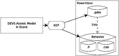
The export of a DEVS atomic model in Ecore produce, first, a file (.pdm) that defines the structure of the model and can be opened by the Model Editor, and secondly, the files that define the behavior (.h and .cpp) so that they can be interpreted by the Atomic Model. The algorithm that generates the code (XEP: XML Ecore to PowerDEVS) was implemented by the authors of the current work and is based on the Saxon XSLT library and the XQuery Processor [57], which is a collection of tools for processing XML documents.
The export process described is shown in Figure 4. In Section 7 two examples of application can be observed.
6 Validation of the Transformation
To validate the application of existing theories and tools about the DEVS models, we need to construct DEVS models from UML SCs models with equivalent behaviors.
In previous sections, we define the transformation by a systematic method and then develop their implementation, but these mechanisms need to be validated in order to increase the credibility of the results.
The validation of a model transformation typically includes properties which involve the syntactic correction of the transformation with respect to its specification language and syntactic correction of models produced by the transformation [58, 59], but few proposals focus on the semantic consistency of the transformation, i.e. the preservation of the correction of the target model in relation to the origin model. In order to do this we can apply both empirical and theoretical (formal) validation methods.
6.1 Empirical Validation
In the context of MDD, software development is based on the refinement of models until they become codes. An example of this is the theory of refinement of Dijkstra [60], widely applied in the area of formal methods. However, it is difficult to adapt the theory to the validation of the model transformation. [61] describes an agile formal proposal for semantic validation specifying the structures of refinement with OCL which are equivalent to those employed in the formal languages. This proposal has the support of the software engineering community, due to the fact that it uses known languages. Generally, refinement is verified by demonstrating that the actual system simulates the abstract system.
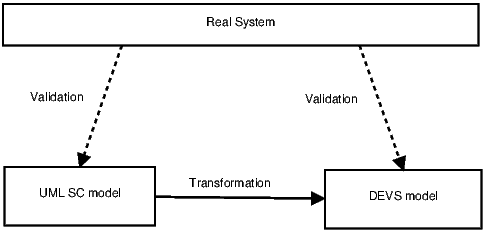
This paper does not specifically propose a refinement, it aims to obtain an equivalent or more general model in the context of simulation systems, in order to take advantage of existing analysis tools. The model validation mechanisms in the field of M&S are clearly suited to our proposal. The model validation methods try to show that the models actually represent the actual system which is one of the most important and difficult tasks faced by a modeler. Therefore, assuming that the validation of the state machine was made, in our proposal, empirical validation of the transformation is limited to the validation of the DEVS model, that is, to determine that the new model resulting from the transformation also models the real system. This is represented in Figure 5.
The modeler should work closely with end users during periods of model development and validation in order to increase the credibility of the model. We can find various model validation strategies in the current literature [62] [63] but the main goals of the validation process are common to all:
- To produce a model that represents a real system behavior, real enough to use it instead of the original system in experimentation and analysis.
- To raise the credibility of the model to an acceptable level so that it is used by those responsible for making decisions.
In the validation process it is important:
- To examine at the model outputs and determine its acceptability, under a variety of configurations of the input parameters. To make this model present a wide variety of statistical results, which should be examined carefully.
- To make the model print the input parameters while analyzing the simulation and verify that their values have not been changed.
- To document the model as much as possible.
- If the operational model is animated, to verify by means of the observation of the simulation that the model imitates the real system.
- To monitor the simulation: tracking specific entities, monitoring of the component values, etc.
- To review the acceptability of the model outputs in detail.
- To calculate certain measures of long-term performance analytically, if possible, and then compare these results with the values that the system provides. his is very important in validating models.
- To use both the real system and the model, the same sets of input data to compare the outputs.
6.2 Proposal for Theoretical Validation
Recent studies describe validation and verification techniques of model transformations. In [64], the idea is to convert a model transformation system into a relational logic specification. The Alloy model analyzer is used to check if any invalid target model is created by the transformation. Other strategies achieve the correction of the transformation by means of the correct-by-construction using transformation patterns [65] or using ontologies [66].
In the context of state transition systems there are simulation and/or bisimulation techniques [67, 39] that could be applied in this work. These techniques attempt to formally prove that a state transition system includes the behavior of another, and vice versa. In our proposal we must demonstrate, in particular, that the behavior of the resulting DEVS model preserves the behavior of the SC, in other words, that the DEVS models behave like the SCs.
A simulation is a binary relation between two systems associated state transition systems where the behavior of one includes the other. A bisimulation is a binary relation between two systems of state transition, which combines systems that behave in the same way. This means, a system simulates another system and vicerversa.
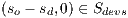
In this work the SCs and DEVS models are state transition systems including time constraints (TLTS). Considering [67], a timed simulation is a binary relation  over a set of states of a TLTS defined as follows:
 is a timed simulation iff
  if
if  then
then 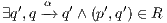
Where  is an external event or permanence time associated with a state.
Two TLTSs are said to be bisimilar iff there exists a bisimulation between their state spaces.
In a TLTS the eventual transition relation defines a transition from state  to state
  that may contain one or more direct transitions labeled. The eventual transition relation (
 ) between
  and
and  on
on  (
( ) is defined as follows:
 iff there is an eventual transition relation from
  to
to  (with
(with  or
or  , which is composed of one or more direct transitions. This represents the following sequence of transitions:
  , proved that the only transition output
  is an even transition time with delay zero, where
  defines zero or more occurrences of transition
  .
.
Weak timed bisimulation
A weak timed simulation [67] is a binary relation  over a set of states of a TLTS. If we have states
  and
and  ,
,  is a weak timed simulation
  iff: if
  , then there is a transition
  .
.
We choose the weak bisimulation relation to validate the transformation from SCs to DEVS, as this relation allows two models to be in simulation relation even with if one of them has some different transitions from the other, provided that these extra transitions are time transition with delay zero.
Preservation of semantics
Given ME = 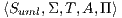 a UML SC, and MA =
  the DEVS atomic model resulting of the transformation. If we define
  as:
as:  where
where  and
and  according to rule 1 defined in section 4.3, then
  is a weak timed bisimulation, which means that MA simulates ME.
Demonstration and a more detailed analysis of the proposal will be considered in the future.
7 Aplication Examples
Two examples are presented in this paper. The first case study shows the simplified operation of an Automatic Banking Machine (ABM). The purpose of this one is to give a general view of the mapping from a UML SC to a DEVS model, showing formal and graphical representations. The second example models the behavior of a control system of an elevator, in order to estimate certain performance variables, such as the average time of movement of each order, utilization factor, etc., or even plot the trajectory. Current available simulation tools for UML SCs do not provide adequate libraries to estimate these variables. This fact has motivated the development of the current work.
Simulations are developed to analyze complex systems. In this first version, the case studies allow the reader to understand the approach proposed in this paper to analyze dynamic systems from a UML diagram state machines. In future extensions contemplate complex systems in order to discover improvements in systems based on analysis by the DEVS simulation models. In Section 7.2, which corresponds to the example of elevator, we describe possible extensions to the case study.
7.1 Automatic Banking Machine (ABM)
The example shows the simplified operation of an ABM, a machine that allow a user to select different types of banking transactions by exchanging data through a magnetic card. In addition, the machine has mechanisms to diagnose failures and provide information to maintenance personnel to perform repairs. Due to space limitations, described below are only the most relevant ABM behaviors. It is considered that the ABM starts off and, once connected to the electrical power supply, a pre-launch automatic test begins, which lasts about 10 seconds. In case of failure the machine goes out of service, otherwise it will be ready for online banking (idle). When the user enters their card, he must authenticate his login with a password or PIN. If the authentication fails, after 30 seconds the ABM goes idle again, ejecting the card entered; otherwise presents an options menu to start a transaction. After the transaction the user decides to make, the user can return to the menu or exit the system. In case of failure, the ABM has a process of diagnosis and repair that maintenance staff is responsible for configuring and executing. This procedure can be performed when the ABM is idle or out of service.
Figure 6 ilustrates the SC of the ABM using the graphical representation of UML 2.4.1.
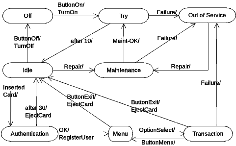
The formal specification of the ABM SC is as follows: (Sc_Cab) =  , where:
 :{Off, Try, Out of Service, Idle, Maintenance, Authentication, Menu, Transaction} ;
 :{ButtonOn, ButtonOff, ButtonExit, Ok, ButtonMenu, InsertedCard, OptionSelect, Failure, Repair, Mant-OK}
  ;
;
 :{(Off
 Try, Off, ButtonOn, true, TurnOn, Try), (Try
 Out Of Service, Failure, true,
  , Out Of Service), (Idle
 Off, Idle, ButtonOff, true, TurnOff, Off), (Idle
 Authentication, Idle, InsertedCard, true,
  , Authentication), (Authentication
  Idle, Authentication,
  , true,
  , Idle), (Try
 Idle, Try,
  , true,
  , Idle), (Idle
 Maintenance, Idle, Repair, true,
  , Maintenance), (Maintenance
 Out of Service, Maintenance, Failure, true,
  , Out of Service), (Maintenance
 Try, Maintenance, Mant-OK , true,
  , Try), (Out of Service
 Maintenance, Out of Service, Repair, true,
  , Maintenance), (Authentication
  Menu, Authentication, Ok, true, RegisterUser, Menu), (Menu
 Idle, Menu, ButtonExit, true, EjectCard, Idle), (Menu
 Transaction, Menu, OptionSelected, true,
  , Transaction), (Transaction
 Menu, Transaction, ButtonMenu, true,
 , Menu), (Transaction
  Out of Service, Transaction, Failure, true,
 , Out of Service), (Transaction
  Idle, Transaction, ButtonExit, true, EjectCard, Idle) } ;
 :{TurnOff, TurnOn, EjectCard, RegisterUser} ;
 :{(Off,
  ), (Try, 10), (Out of Service,
  ), (Idle,
  ), (Maintenance,
  ), (Authentication, 30), (Menu,
  ), (Transaction,
  )} .
)} .
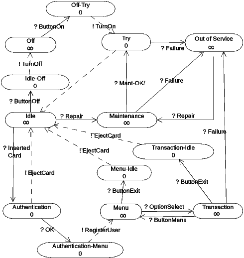
From UML ABM to DEVS ABM
The execution of the transformation rules in QVT-R takes as argument the ABM UML model in Ecore format and creates a DEVS atomic model. Figure 7 shows a diagram of the resulting DEVS atomic model. Although DEVS models do not have a standardized graphical notation, because the sets may have infinite cardinality, in this case it is possible to plot the model because the number of processed elements is finite. By convention, internal transitions are drawn with dotted lines and the output  function is represented implicitly on internal transitions specifying the output as a function of the source state, for example, !EjectCard. The other elements are intuitive in the diagram.
Note that the transformation of the transitions that are triggered by the occurrence of external events, and that have actions as output, generate an intermediate state with life time  , to produce immediate output action. For example, the transition going from state Off to state Try produces the intermediate state Off-Try; when this is reached an internal transition is triggered immediately (because the lifetime is zero) that changes the the ABM to the state Try, and also, launches out the action !TurnOn (
 (Off-Try) = TurnOn).
The formal specification of the resulting DEVS ABM atomic model (Devs_Cab) is as follows:
Devs_Cab = 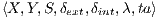 , where:
 :{ButtonOff, ButtonExit, Ok, ButtonMenu, InsertedCard, OptionSelect, ButtonOn, Failure, Repair, Off-Try, Idle-Off, Authentication-Menu, Menu-Idle,Transaction-Idle}
 :{TurnOff, EjectCard, RegisterUser, TurnOn}
 :{(d,
:{(d,  )
)  d
d  {Off, Try, Out of Service, Idle, Maintenance, Authentication, Menu, Transformation}
  }
}
The external transitions are:
 (((Off,
  ), t
), t ), ?ButtonOn) = (Off-Try, 0)
 (((Try,
  ), t
), t ), ?Failure) = (Out of Service,
  )
)
 (((Out of Service,
  ), t
), t ), ?Repair) = (Maintenance,
  )
)
 (((Maintenance,
  ), t
), t ), ?Failure) = (Out of Service,
  )
)
 (((Idle,
  ), t
), t ), ?Repair) = (Maintenance,
  )
)
 (((Idle,
  ), t
), t ), ?ButtonOff) = (Idle-Off, 0)
 (((Idle,
  ), t
), t ), ?InsertedCard) = (Authentication, 30)
 (((Authentication,
  ), t
), t ), ?Ok) = (Authentication-Menu, 0)
 (((Menu,
  ), t
), t ), ?ButtonExit) = (Menu-Idle, 0)
 (((Menu,
  ), t
), t ), ?OptionSelect) = (Transaction,
  )
)
 (((Transaction,
  ), t
), t ), ?ButtonMenu) = (Menu,
  )
)
 (((Transaction,
  ), t
), t ), ?Failure) = (Out of Service,
  )
)
 (((Transaction,
  ), t
), t ), ?ButtonExit) = (Transaction-Idle, 0)
The internal transition are:
 (Off-Try,
  ) = (Try, 10)
 (Try,
(Try,  ) = (Idle,
  )
)
 (Idle-Off,
  ) = (Off,
  )
)
 (Authentication,
  ) = (Idle,
  )
)
 (Authentication-Menu,
  ) = (Menu,
  )
)
 (Menu-Idle,
  ) = (Idle,
  )
)
 (Transaction-Idle,
  ) = (Idle,
  )
)
The output function is defined as:
 (Off-Try,
  ) = !TurnOn
 (Idle-Off,
  ) = !TurnOff
 (Authentication-Menu,
  ) = !RegisterUser
 (Menu-Idle,
  ) = !EjectCard
 (Transaction-Idle,
  ) = !EjectCard
From DEVS ABM in Ecore to PowerDEVS
The DEVS ABM atomic model in Ecore resulting from the transformation, it is translated into C++ code by the XEP algorithm developed by the authors in order to be interpreted and simulated by PowerDEVS. According to the description in Section 5.2, the files that define the structure (.pdm) and behavior (.h, .cpp) of the model are generated. The following code shows the ABM.pdm generated file:
Coupled {
Type = Root
Name = CAB
Ports = 0; 0
Description =
Graphic {
Position = 0; 0
Dimension = 600; 600
Direction = Right
Color = 15
Icon = Window = 5000; 5000; 5000; 5000
}
Parameters {
}
System {
Atomic {
Name = CAB
Ports = 1 ; 1
Path = discrete\CAB.h
Description = Atomic DEVS model
Graphic {
Position = -6105 ; -2610
Dimension = 675 ; 720
Direction = Right
Color = 15
Icon = None
}
Parameters {
}
}
}
}
The C++ code corresponding to the generated header file ABM.h is displayed below:
#if !defined CAB
#define CAB
#include "simulator.h"
#include "event.h"
#include "stdarg.h"
class CAB: public Simulator {
// Declare the state,
// output variables
// and parameters
char *s;
double sigma;
char *y;
#define INF 1e20
public:
CAB(const char *n): Simulator(n) {};
void init(double, ...);
double ta(double t);
void dint(double);
void dext(Event , double );
Event lambda(double);
void exit();
};
#endif
Finally, below are shown just the relevant parts of the generated C++ code corresponding to the behavior of the DEVS ABM in Ecore (CAB.cpp):
#include "CAB.h"
void CAB::init(double t,...) {
//The ’parameters’ variable contains the parameters
// transferred from the editor.
va_list parameters;
va_start(parameters,t);
//To get a parameter: %Name% = va_arg(parameters,%Type%)
//where:
// %Name% is the parameter name
// %Type% is the parameter type
s = "Off";
sigma = INF;
}
double CAB::ta(double t) {
//This function returns a double.
return sigma;
}
void CAB::dint(double t) {
if (strcmp(s,"Try")== 0) {
s = "Idle";
sigma = INF
};
if (strcmp(s,"Autentication")== 0) {
s = "Idle";
sigma = INF
};
if (strcmp(s,"Off-Try")== 0) {
s = "Try";
sigma = 10.0;
};
...
}
void CAB::dext(Event x, double t) {
//The input event is in the ’x’ variable.
//where:
// ’x.value’ is the value (pointer to void)
// ’x.port’ is the port number
// ’e’ is the time elapsed since last transition
if ((strcmp(s,"Try")== 0) && (strcmp((char*)x.value,"Failure")== 0)) {
s = "OutofService";
sigma = INF;
};
if ( (strcmp(s,"Idle")== 0) && (strcmp((char*)x.value,"InsertedCard")== 0)) {
s = "Autentication";
sigma = 30.0;
};
...
}
Event CAB::lambda(double t) {
//This function returns an Event:
// Event(%Value%, %NroPort%)
//where:
//%Value% points to the variable which contains the value.
//%NroPort% is the port number (from 0 to n-1)
if (strcmp(s,"Off-Try")== 0) {
y = "TurnOn";
return Event(y,0);
};
if (strcmp(s,"Idle-Off")== 0) {
y = "TurnOff";
return Event(y,0);
};
...
}
void CAB::exit() {
//Code executed at the end of the simulation.
}
7.2 Control System of an Elevator
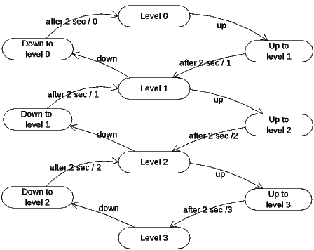
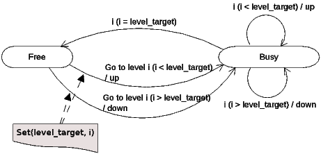
Consider a simple elevator that can be commanded by the events up and down. Each level of the building has a sensor that indicates the presence of the elevator, so that the output of the “system elevator” are the events produced by these sensors. The elevator goes up and down at constants speeds of 1 meter per second, the distance between one level and another is 2 meters and the building has 4 levels.
The elevator is commanded by a controller that receives events indicating the current level of the elevator. Whenever an event arrives, verifies if the elevator should continue going up or down. Upon reaching the target level, it doesn’t send any other signal to the elevator, making it to remain at the current level.
A possible extension to the problem is to attach a generator to the controller which generates the elevator destinations as Go to level i. Each time the controller sends a Free signal, the generator, after a short time (delay), must determine the new level to which the elevator should be directed. Collected data indicates that delays follows an exponential probability distribution with mean 4 seconds, and destination levels have equal probability of being selected.
It is of interest in this problem to get, through simulations, graphics of the elevator trajectory and know its utilization factor(usage time / total time). Future extensions may include the management of a queue of orders to the elevator and assess, for example, the average waiting time of orders (time between the occurrence of the order and the beginning of the movement towards the target); and even composing this operations to form a system of several elevators.
For clarity, we model the problem by designing three UML state machines: i) SC UML for the elevator, ii) SC UML for the controller, and iii) SC UML for the generator. Figure 8 and Figure 9 ilustrate the SCs of the elevator and controller respectively, using the graphical representation of UML 2.4.1.
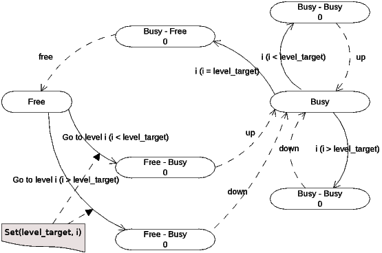
After applying the transformation rules presented in Section 5.1, the resulting DEVS models in Ecore format are shown in Figure 10 and Figure 11. Then, through the algorithm XEP, C++ code is generated corresponding to PowerDEVS models (.pdm, .h and .cpp files) to be handled by this tool. We call PowerDEVS models to models that satisfy the metamodel of Figure 3.
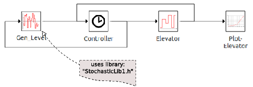
Simulation tools, particularly PowerDEVS, contain a lot of libraries that help enrich the models to be analyzed and discover properties about them. In the present example, as an initial step, the generated models of the generator, controller and elevator are connected, and later, PowerDEVS libraries (StochasticLib1.h) are used to plot and generate samples of, an exponential distribution for the delays, and a uniform distribution for the building leves, as can be seen in Figure 12. The StochasticLib1.h library implements the generation of samples of a variety of probability distributions commonly used in discrete event simulation models.
After several runs of the system and using the technique of confidence interval for the outputs it was established that on average the utilization factor of the elevator is 0,34 (34%) and their confidence limits are  . Likewise, analyzing the graphics and records (log files) determines that the elevator moves on average
  levels for each order, this corresponds to 2.64 sec. This measurement makes more sense in a possible extension of the case study, for example, considering waiting lines with different policies (disciplines) and multiple elevators working together. In this case, if the discipline of the queues changes, the amount of movement of the elevators will be modified. It is difficult to analyze this with current available execution tools for UML SCs.
8 Conclusion and Future Work
MDD is an approach with the potential to make development more efficient and obtain more reliable results, since, among other things, it enables the verification of systems in early stages of development offering greater control. Many of MDD techniques use UML, incorporated as a de facto standard language in academic and industrial areas, which allows the description of many aspects of a system. In particular, UML statecharts provide a mechanism to specify the behavior of systems using a graphical representation. These diagrams are compact, expressive and provide the ability to model not only simple but also complex reactive systems. Multiple tools support the latest versions of UML, which generally provide graphical features that facilitate the modeling of systems. However, they lack the ability to execute and simulate dynamic models. This limits the analysis of the behavior of systems in real scenarios. DEVS is founded on the principles of systems theory and its development through component-based engineering. With the advances of UML in recent years, the community around DEVS has devoted efforts to define a mapping between UML and DEVS elements. It is known that DEVS is more rigorous and expressive than UML, but due to the manipulation of potentially infinite sets which a model can contain, it lacks a graphical notation which is required by industry professionals. The combination of graphic virtues of UML with the powerful simulation tools of DEVS models led to the current proposal. Some research groups have addressed various proposals for this important relation between DEVS and UML, but none has a formal solution or an implementation based on the definition of metamodels using standards.
This work presents a mechanism for closing the gap between two formalisms with different tools and technologies, different theoretical bases, but united by a common purpose, which is to provide solutions to real problems through the creation and analysis of abstract models. A process of model transformation that maps elements from UML SCs to elements of DEVS models is defined. This is achieved by exploiting the graphic qualities of one, the specificity and rigor of the other, resulting in a simulation model that can be executed and analyzed by a large number of specific tools. The transformation was defined as a set of rules by cases and was implemented using QVT-R, a language standardized by the OMG. The UML 2.4.1 metamodel in Ecore format is used and the metamodel of the DEVS formalism, also in Ecore, is defined. The result of the transformation is a DEVS model in Ecore format that satisfies its corresponding metamodel. This model provides a sufficient set of information that can be exported and executed by different existing DEVS simulation tools and engines, in particular PowerDEVS. Furthermore, two examples of application to analyze the behavior of an automatic banking machine and a control system of an elevator are presented and analyzed. These case studies show the usefulness of the proposed approach.
This research is part of a comprehensive project that in the future will address the following extensions: i) development of a direct transformation of UML statecharts with composite states to DEVS models; ii) incorporation of more elements of UML to the SCs, including their transformations to elements of a DEVS model; iii) extension of the DEVS formalism with conditional transitions, in order to enable adding decision elements to the flow of the system; iv) exportation of the resulting Ecore DEVS models to other simulation tools; v) process evaluation with complex cases studies; vi) construction of a tool that covers the complete process of transformation, execution and analysis; vii) development of a deeper analysis of the validation mechanism of transformation; viii) implementation of the model-to-text (M2T) transformation using the OMG standards, in particular the MOF Model To Text Transformation Language (MOFM2T); and ix) development of an editor that allows the use of only those elements of the UML SCs that are considered in the transformation, preserving the semantics and design constraints defined in the latest version of UML.
References
[1] S. J. Mellor, A. N. Clark, and T. Futagami, “Guest editors’ introduction: Model-driven development,” IEEE Software, vol. 20, no. 5, pp. 14–18, 2003.
[2] B. Selic, “The pragmatics of model-driven development,” IEEE Softw., vol. 20, no. 5, pp. 19–25, 2003.
[3] T. Stahl, M. Voelter, and K. Czarnecki, Model-Driven Software Development: Technology, Engineering, Management. John Wiley & Sons, 2006.
[4] R. France and B. Rumpe, “Model-driven development of complex software: A research roadmap,” in 2007 Future of Software Engineering. IEEE Computer Society, 2007, pp. 37–54.
[5] S. Beydeda, M. Book, V. Gruhn et al., Model-driven software development. Springer, 2005, vol. 15.
[6] J. Miller and J. Mukerji, “Mda guide version 1.0.1,” Object Management Group (OMG), Tech. Rep., 2003.
[7] Object Management Group, Object Management Group Std., Last access: May 2015. [Online]. Available: http://www.omg.org
[8] OMG Unified Modeling Language (OMG UML), Superstructure, Version 2.4.1, Object Management Group Std., Rev. 2.4.1, 2011. [Online]. Available: http://www.omg.org/spec/UML/2.4.1
[9] J. Rumbaugh, I. Jacobson, and G. Booch, Unified Modeling Language Reference Manual, The (2Nd Edition). Pearson Higher Education, 2004.
[10] B. P. Zeigler and S. Vahie, “Devs formalism and methodology: Unity of conception/diversity of application,” in Proceedings of the 25th Conference on Winter Simulation, ser. WSC ’93. New York, NY, USA: ACM, 1993, pp. 573–579. [Online]. Available: http://doi.acm.org/10.1145/256563.256724
[11] G. Wainer and P. Mosterman, Discrete-Event Modeling and Simulation: Theory and Applications, ser. Computational Analysis, Synthesis, and Design of Dynamic Systems. Taylor & Francis, 2010. [Online]. Available: http://books.google.com.uy/books?id=WQvzk7ZnwHkC
[12] Z. Cirino, Devs. CIV, 2012. [Online]. Available: http://books.google.com.uy/books?id=-BxCuAAACAAJ
[13] B. Zeigler, H. Praehofer, and T. Kim, Theory of Modeling and Simulation: Integrating Discrete Event and Continuous Complex Dynamic Systems. Academic Press, 2000. [Online]. Available: http://books.google.com.uy/books?id=REzmYOQmHuQC
[14] H. G. Molter, “Discrete event system specification,” in SynDEVS Co-Design Flow. Springer Fachmedien Wiesbaden, 2012, pp. 9–42. [Online]. Available: http://dx.doi.org/10.1007/978-3-658-00397-5_2
[15] J. Wang, Handbook of Finite State Based Models and Applications, 1st ed. Chapman & Hall/CRC, 2012.
[16] D. Harel, “Statecharts: A visual formalism for complex systems,” Sci. Comput. Program., vol. 8, no. 3, pp. 231–274, 1987.
[17] OMG, Meta Object Facility (MOF) 2.0 Query/View/Transformation Specification, Version 1.1, Object Management Group Std., Rev. 1.1, 2011. [Online]. Available: http://www.omg.org/spec/QVT/1.1/
[18] F. Bergero and E. Kofman, “Powerdevs: A tool for hybrid system modeling and real-time simulation,” Simulation, vol. 87, no. 1-2, pp. 113–132, Jan. 2011. [Online]. Available: http://dx.doi.org/10.1177/0037549710368029
[19] A. Gonzalez, C. D. Luna, R. Cuello, M. Perez, and M. Daniele, “Metamodel-based transformation from UML state machines to DEVS models,” in XL Latin American Computing Conference, CLEI 2014, Montevideo, Uruguay, September 15-19, 2014. IEEE, 2014, pp. 1–12. [Online]. Available: http://dx.doi.org/10.1109/CLEI.2014.6965145
[20] IBM Rational Rose, IBM, Last access: May 2015. [Online]. Available: http://www.ibm.com/developerworks/rational/products/rose
[21] J. Russell and R. Cohn, Ibm Rational Rose Xde. Book on Demand, 2012. [Online]. Available: http://books.google.com.uy/books?id=vIecMQEACAAJ
[22] Poseidon for UML, Last access: May 2015. [Online]. Available: http://www.gentleware.com/new-poseidon-for-uml-8-0.html
[23] S. Bendre and H. S. Sarjoughian, “Discrete-event behavioral modeling in sesm: Software design and implementation,” in Advanced Simulation Technology Conference, 2005, pp. 23–28.
[24] P. P. Vladimir and P. Slavícek, “Towards devs meta language,” in Industrial Simulation Conference, 2006, pp. 69–73.
[25] S. Mittal, J. L. Risco-Martín, and B. P. Zeigler, “Devsml: Automating devs execution over soa towards transparent simulators,” in Proceedings of the 2007 Spring Simulation Multiconference - Volume 2, ser. SpringSim ’07. San Diego, CA, USA: Society for Computer Simulation International, 2007, pp. 287–295. [Online]. Available: http://dl.acm.org/citation.cfm?id=1404680.1404725
[26] G. J. Badros, “Javaml: a markup language for java source code.” Computer Networks, vol. 33, no. 1-6, pp. 159–177, 2000. [Online]. Available: http://dblp.uni-trier.de/db/journals/cn/cn33.html#Badros00
[27] J. de Lara and H. Vangheluwe, “Using atom3 as a meta-case tool.” in ICEIS, 2002, pp. 642–649. [Online]. Available: http://dblp.uni-trier.de/db/conf/iceis/iceis2002.html#LaraV02
[28] K. Choi, S. Jung, H. Kim, D.-H. Bae, and D. Lee, “Uml-based modeling and simulation method for mission-critical real-time embedded system development,” in IASTED Conf. on Software Engineering, P. Kokol, Ed. IASTED/ACTA Press, 2006, pp. 160–165.
[29] S. Y. Hong and T. G. Kim, “Embedding uml subset into object-oriented devs modeling process,” in Society of Modeling and Computer Simulation International, 2004, pp. 161 – 166.
[30] D. Zinoviev, “Mapping DEVS models onto UML models,” CoRR, vol. abs/cs/0508128, 2005. [Online]. Available: http://arxiv.org/abs/cs/0508128
[31] D. Huang and H. S. Sarjoughian, “Software and simulation modeling for real-time software-intensive systems,” in DS-RT. IEEE Computer Society, 2004, pp. 196–203.
[32] B. P. Douglass, Real-Time UML: Developing Efficient Objects for Embedded Systems. Boston, MA, USA: Addison-Wesley Longman Publishing Co., Inc., 1997.
[33] H. Gomaa, Software Modeling and Design: UML, Use Cases, Patterns, and Software Architectures, 1st ed. New York, NY, USA: Cambridge University Press, 2011.
[34] S. Schulz, T. Ewing, and J. Rozenblit, “Discrete event system specification (devs) and statemate statecharts equivalence for embedded systems modeling,” in ECBS. IEEE Computer Society, 2000, p. 308.
[35] D. Harel and M. Politi, Modeling Reactive Systems with Statecharts: The Statemate Approach, 1st ed. New York, NY, USA: McGraw-Hill, Inc., 1998.
[36] A. Tolk and J. A. Muguira, “M&s within the model driven architecture,” in Interservice/Industry Training, Simulation, and Education Conference, 2004.
[37] R. Pasqua, D. Foures, A. Vincent, and A. Nketsa, “From sequence diagrams uml 2.x to fd-devs by model transformation,” in European Simulation and Modelling Conference, Essen, Germany, Oct. 2012, pp. 37–43 N° 12 481. [Online]. Available: https://hal.archives-ouvertes.fr/hal-00781084
[38] J. Hu, L. Huang, B. Cao, and X. Chang, “Extended DEVSML as a model transformation intermediary to make UML diagrams executable,” in The 26th International Conference on Software Engineering and Knowledge Engineering, Hyatt Regency, Vancouver, BC, Canada, July 1-3, 2013., 2014, pp. 314–317.
[39] H. Saadawi and G. A. Wainer, “Principles of discrete event system specification model verification.” Simulation, vol. 89, no. 1, pp. 41–67, 2013. [Online]. Available: http://dblp.uni-trier.de/db/journals/simulation/simulation89.html#SaadawiW13
[40] J. L. Risco-Martín, J. M. de la Cruz, S. Mittal, and B. P. Zeigler, “eudevs: Executable uml with devs theory of modeling and simulation.” Simulation, vol. 85, no. 11-12, pp. 750–777, 2009. [Online]. Available: http://dblp.uni-trier.de/db/journals/simulation/simulation85.html#Risco-MartinCMZ09
[41] J. Russell and R. Cohn, Scxml. Book on Demand, 2012. [Online]. Available: http://books.google.com.uy/books?id=zXDGMgEACAAJ
[42] S. Mittal, B. Zeigler, and M. Hwang, W3C XML Schema for Finite Deterministic (FD) DEVS Models, Std., Last access: May 2015. [Online]. Available: http://www.saurabh-mittal.com/fddevs/
[43] B. P. Zeigler and H. Sarjoughian, “Introduction to devs modeling and simulation with java: A simplified approach to hla-compliant distributed simulations,” Arizona Center for Integrative Modeling and Simulation, 2000.
[44] ATL Transformation Language, Last access: May 2015. [Online]. Available: http://www.eclipse.org/atl
[45] OMG Meta Object Facility (MOF) Core Specification, Version 2.4.1, Object Management Group Std., Rev. 2.4.1, 2011. [Online]. Available: http://www.omg.org/spec/MOF/2.4.1
[46] Medini QVT, ikv++ Technologies, Last access: May 2015. [Online]. Available: http://www.ikv.de/
[47] D. Steinberg, F. Budinsky, M. Paternostro, and E. Merks, EMF: Eclipse Modeling Framework 2.0, 2nd ed. Addison-Wesley Professional, 2009.
[48] Ecore metamodel specification, Object Management Group, Last access: May 2015. [Online]. Available: http://download.eclipse.org/modeling/emf/emf/javadoc/2.9.0/org/eclipse/emf/ecore/package-summary.html
[49] MOLA Tool Architecture, Last access: May 2015. [Online]. Available: http://mola.mii.lu.lv
[50] A. Wasowski, “Flattening statecharts without explosions,” SIGPLAN Not., vol. 39, no. 7, pp. 257–266, Jun. 2004. [Online]. Available: http://doi.acm.org/10.1145/998300.997200
[51] B. P. Zeigler, T. G. Kim, and H. Praehofer, Theory of Modeling and Simulation, 2nd ed. Orlando, FL, USA: Academic Press, Inc., 2000.
[52] M. von der Beeck, “A structured operational semantics for uml-statecharts,” Software and Systems Modeling, vol. V1, no. 2, pp. 130–141, December 2002. [Online]. Available: http://dx.doi.org/10.1007/s10270-002-0012-8
[53] H. Cho and Y. Cho, DEVS-C++ Reference Guide, The University of Arizona, 1997.
[54] T. G. Kim, DEVSim++ User’s Manual. C++ Based Simulation with Hierarchical Modular DEVS Models, Korea Advance Institute of Science and Technology, 1994.
[55] G. Wainer, “Cd++: A toolkit to develop devs models,” Softw. Pract. Exper., vol. 32, no. 13, pp. 1261–1306, 2002. [Online]. Available: http://dx.doi.org/10.1002/spe.482
[56] J.-B. Filippi and P. Bisgambiglia, “Jdevs: an implementation of a devs based formal framework for environmental modelling,” in Environmental Modelling and Software, 2004, pp. 261–274.
[57] M. Kay, SAXON. The XSLT and XQuery Processor, Saxonica, Last access: May 2015. [Online]. Available: http://saxon.sourceforge.net
[58] J.-M. Mottu, B. Baudry, and Y. L. Traon, “Reusable mda components: A testing-for-trust approach.” in MoDELS, ser. Lecture Notes in Computer Science, O. Nierstrasz, J. Whittle, D. Harel, and G. Reggio, Eds., vol. 4199. Springer, 2006, pp. 589–603. [Online]. Available: http://dblp.uni-trier.de/db/conf/models/models2006.html#MottuBT06
[59] J. M. Küster, “Definition and validation of model transformations.” Software and System Modeling, vol. 5, no. 3, pp. 233–259, 2006. [Online]. Available: http://dblp.uni-trier.de/db/journals/sosym/sosym5.html#Kuster06
[60] E. W. Dijkstra, A Discipline of Programming, 1st ed. Upper Saddle River, NJ, USA: Prentice Hall PTR, 1997.
[61] C. Pons and D. Garcia, “A lightweight approach for the semantic validation of model refinements,” Electronic Notes in Theoretical Computer Science, vol. 220, no. 1, pp. 43–61, December 2008. [Online]. Available: http://dx.doi.org/10.1016/j.entcs.2008.11.005
[62] J. Banks, J. S. Carson, B. L. Nelson, and D. M. Nicol, Discrete-Event System Simulation (5rd Edition), 5th ed. Prentice Hall, 2010.
[63] R. G. Sargent, “Verifying and validating simulation models,” in Proceedings of the 2014 Winter Simulation Conference, Savannah, GA, USA, December 7-10, 2014, 2014, pp. 118–131. [Online]. Available: http://dx.doi.org/10.1109/WSC.2014.7019883
[64] X. Wang, F. Büttner, and Y. Lamo, “Verification of graph-based model transformations using alloy,” ECEASST, vol. 67, pp. 113–129, 2014. [Online]. Available: http://journal.ub.tu-berlin.de/eceasst/article/view/943
[65] K. Lano, S. Kolahdouz-Rahimi, I. Poernomo, J. Terrell, and S. Zschaler, “Correct-by-construction synthesis of model transformations using transformation patterns,” Softw. Syst. Model., vol. 13, no. 2, pp. 873–907, May 2014. [Online]. Available: http://dx.doi.org/10.1007/s10270-012-0291-7
[66] S. Roser and B. Bauer, “Automatic generation and evolution of model transformations using ontology engineering space,” Journal on Data Semantics XI, vol. 5383, pp. 32–64, 2014.
[67] L. Aceto, A. Ingólfsdóttir, K. G. Larsen, and J. Srba, Reactive Systems: Modelling, Specification and Verification. New York, NY, USA: Cambridge University Press, 2007.
 Todo el contenido de esta revista, excepto dónde está identificado, está bajo una Licencia Creative Commons
Montevideo - Uruguay.
Tel: (598) 2711 4244 int. 124

CLEIejEditor@fing.edu.uy