


Servicios Personalizados
Revista

Articulo
 Inglés (pdf)
 Articulo en XML
 Referencias del artículo
Links relacionados
Compartir

 Permalink
CLEI Electronic Journal
versión On-line ISSN 0717-5000
CLEIej vol.17 no.2 Montevideo ago. 2014
Abstract
The most important result to standardize the notation for graphical representation of Business Processes (BPs) is the Business Process Model and Notation (BPMN). Despite the BPs modeled with BPMN being able to support business designers, BPMN models are not appropriate to support the analysis phase. BPMN models have no formal semantics to conduct qualitative analysis (validation and verification). In this work is presented how Model Checking (MC) verification technique for software and Timed Automata (TA) formal language are integrated within a formal verification approach to check BPs modeled with BPMN. Also, are introduced a set of guideline to transform BPMN models into TA. The use of our approach allow to business analysts and designers to perform evaluation (i.e., qualitative analysis) of BPs, based on the formal specification of BP–task model with TA. The application of the approach is aimed to evaluate the behavior of the BP–task model with respect to business performance indicators (for instance, service time, waiting time or queue size) derived from business needs, as is shown in an instance of an enterprise–project related to Customer Relationship Management.
Spanish Abstract:
El resultado más importante para estandarizar la notación para la representación gráfica de los Procesos de Negocio (PNs) es la Business Process Model and Notation (BPMN). A pesar de que los PNs modelados con BPMN pueden soportar a los diseñadores de negocio, los modelos BPMN no son apropiados para apoyar la fase de análisis. Los Modelos BPMN no tienen la semántica formal para llevar a cabo el análisis cualitativo (validación y verificación). En este trabajo se presenta cómo la técnica de Verificación Automática (VA) para software y el lenguaje formal de Autómatas Temporizados (AT) se integran dentro de un enfoque de verificación formal para comprobar PNs modelados con BPMN. Además, se introducen un conjunto de directrices para transformar modelos BPMN en TA. El uso de nuestro enfoque permite a los analistas y diseñadores de negocios realizar la evaluación (es decir, el análisis cualitativo) de PNs, basada en la especificación formal del modelo de tarea del PN con TA. La aplicación del enfoque está dirigido a evaluar el comportamiento del modelo de tarea del PN con respecto a los indicadores del desempeño del negocio (por ejemplo, tiempo de servicio, tiempo de espera tamaño de la cola) derivado de las necesidades del negocio, como se muestra en una instancia de un proyecto empresarial relacionado con la Gestión de Relaciones con el Cliente.
Keywords: Model checking, Timed automata, Task model, Business process, Qualitative analysis.
Spanish keywords: Verificación automática, Autómata temporizado, Modelo de tareas, Proceso de negocio, Análisis cualitativo.
Received 2013-11-15, Revised 2014-02-20, Accepted 2014-02-20
Model Checking (MC) is a formal verification technique that enables exhaustive and automatic checking of whether or not a model meets a given specification [ 1]. Thus, applying MC to Business Process (BP) verification helps to solve problems as bottlenecks and deadlocks. To apply the MC technique, the BPs need to be described in a formal language. However, the Business Process Model and Notation (BPMN) [ 2], which is a standard notation for describing BPs in the early phases of development, does not have formal semantics. BPMN models do not provide mechanisms to quantify the computational/human effort required to perform the activities, nor the response time of work when resources (e.g., a BP–worker) are concurrently shared among multiple processes. In previous works [ 3, 4, 5], some approaches were proposed for the formalization of BPMN; however, they did not deal well enough with temporal and concurrency constraints.
The temporal perspective is a contributing factor to both the design–time and the run–time of a BP. At BP design–time, the temporal perspective allows the modeler to explicitly specify temporal constraints and dependencies to ensure that all temporal requirements of the process are met. At run–time, the temporal perspective of the BP specification leads to the ability to precisely schedule a BP. The idea of obtaining directly an executable model (i.e., a BP–task model) from a BP conceptual —a BP descriptive model based on qualitative assumptions about its elements, their interrelations, and BP boundaries— one (e.g., a BPMN diagram) has taken us to use an instantiation of the formal verification approach explained in [ 6] integrated with Timed Automata (TA) as was introduced in [7]. In particular, the formal verification approach explained in [ 6] focus on the perspective of temporal and concurrency constraints on BPs, allowing the correctness of BP–task models through the MC technique to support the analysis of the satisfaction of business temporal constraints and dependencies.
In this paper, is proposed an approach based on the MC techniques for the formal verification of BPs based on the construction of a BP–task model as a TA–network (i.e., at design–time), which conform with the semantics of the BPMN standard [ 2] and the business temporal and concurrency constraints. In this way, the behavioral aspects and temporal constraints in a BP–task model are simulated and verified (i.e., at run–time) using the Uppaal [ 8] MC tool as we will show in the sequel by the application to an instance of Customer Relationship Management (CRM) strategy. First, we provide a set of mapping guidelines to transform BPMN process models into TA that can be verified by Uppaal [ 8]. Next, the instantiation of the formal verification approach introduced in [ 7] is applied to verify the corresponding BP–task model. As a result, BP designers can verify BPs efficiently through the following steps: (1) description of BPs and their constraints with a formal temporal logic, (2) systematic transformation into TA systematically with the transformation guidelines, and (3) running of the Uppaal model checker with the BP–task model and properties to be verified. With the verification results, the business analysts and designers can perform improvements to BPs and adjustment of their constraints (i.e., return to step (1)) depending on the results obtained. This helps to eliminate serious problems related to temporal and concurrency constraints in the early phases of development and to assure the quality of BPs models.
Since our approach is aimed at representing BP–task model concurrent aspects, the contribution is more focused on verification of consistency and synchronization of concurrent tasks which exist in BP–task model than in other BPs oriented validations. According to our approach, the verification of structured BP–task model can be carried out with correctness by only starting from the verification of the simplest TAs. As final remark, our proposal can be adapted to other BP languages and standards which allow the transformation of the properties to verify and the modelling elements of BP–task model into formal language constructs supported by MC tools. See [ 9] to review an example of an adaptation of our approach to a BP–task model derived from BPs modeled with BP UML stereotypes and [ 6] to check the version of formal verification approach that integrates BPMN notation with the formal language Communicating Sequential Processes + Time (CSP+T).
The paper’s remainder is organized as follows. Section 2 presents the related work. Section 3 introduces the three topics required to the understanding of this work: the BPMN notation, the TA theory with the MC technique, and the Clocked Computation Tree Logic (CCTL). Section 4 explains the BP–task model verification approach. The defined guidelines for transforming BPMN to TA are presented in Section 5. Section 6 shown an application example related to the CRM business, while the concluding remarks are made in Section 7.
Reviewing the literature, we found few works to allow us to establish the state of the art in specifying and verifying the temporal perspective in BPs using BPMN. In [ 3] is presented a extend survey of existing proposal verification techniques of BPMN diagrams and compare them among each other with respect to motivations, methods, and logics. Nevertheless, none of cited works take into account the temporal perspective of the behavior of a BP. In addition, these works do not combine the modeling of BPs with the analysis/design of BP–task models and verification activities.
For the purposes of this paper, it is worth mentioning the work in [ 5], due to that it is an extension of BPMN, called Time–BPMN, with a large set of required temporalities. This work presents a classification of flexible and inflexible temporal constraints and temporal dependencies. This extensions does not permit to model temporal constraints relating to the duration of the BP activities. Notwithstanding, Time–BPMN [ 5] is limited to the specification phase since no verification mechanism of temporal constraints is provided.
It is also important to mention the work in [ 10], which proposes a formal specification of BPMN with TA. The authors extend BPMN to handle temporal, concurrency, and resource constraints. They also provide an automatic mapping of the extended BPMN onto TA. This approach aims at verifying some features, such as deadlocks and bottlenecks; but the scope of this paper is limited to a small subset of BPMN elements. The extension provided in this work permits to specify temporal constraints related to only one activity within the BP model and does not consider timed properties related to a set of activities, such as inter–activities temporal constraints.
Finally, it is worth mentioning the work in [ 11], due to that it incorporates the concept of controllability —capability of executing a workflow for any possible duration of tasks— and its evaluation at design–time; i.e., it establishes the importance of controlling the task run–time and other notational elements of BPMN as part of BP analysis [ 11]. With the work presented here, is incorporated in a practical way the concept of controllability, which allows us to analyze the decisions made at design–time of a BP–task model associated to a specific BP from the behavior of the elements (BP–workers specifically) that make it up at run–time, as part of a verification approach.
The work presented here is aimed at giving a systemic, integrated vision of analysis, design and verification tasks of BPs, by incorporating the use of TA and MC tools in the BP–task model development cycle, to allow us to obtain the expected result: the verification of the complete BP–task model associated to a specific BP. Following the steps mentioned in the introduction, BP analyst and designers can verify BPs efficiently. In this way, we take full advantage of the strengths that a formalization of the behavioral and temporal aspects of BPMN can offer to the BP analysis both at design–time and run–time, integrating verification software tools.
3.1 Business Process Model and Notation (BPMN)
The Business Process Modeling Notation (BPMN) provides organisations with the capability of specifying and depicting their BPs using a graphical notation with an emphasis on control–flow. The latest version of BPMN [ 2] aims to be a visual language to communicate BPs in a standard manner. The BPMN Business Process Diagram (BPD) incorporates constructs adequate to BP modelling, such as events, tasks, gateways and flows, and defines more advanced constructs, such as task looping, parallel multinstances, inclusive OR decission, subprocesses and exception handling. And hence, a language of this type will include the modelling concepts necessary to describe certain aspects of a BP at a certain abstraction level. Figure 1 shows the main BPMN notational elements as they are represented in BPDs.
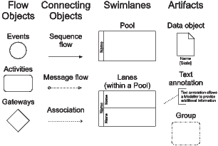
An event is something that happens during the course of a process and affects the flow of the process. The start event indicates where a process will start, and end event indicates where a process will end. An activity is a generic term for work performed in the process; it can be atomic (called task) or compound. In this work, the term activity refers to an atomic activity or task. A sequence flow is used to show the order in which activities will be performed. A gateway is used to control the divergence and convergence of sequence flows. Gateways can have several behavior controls and each type of control affects both the incoming and outgoing flow: exclusive, parallel, and inclusive gateways. In a parallel between BPMN objects and the workflow terminology, an exclusive gateway corresponds to a XOR-split/join, a parallel gateway corresponds to an AND-split/join, and an inclusive gateway corresponds to an OR-split/join. A Pool typically represents an organization or business entity and a Lane represents a department or BP–worker within that organization, or other modelling entities like functions, applications, and systems. Both, pools and lanes, represent BP participants. A message flow represents the communication between two asynchronous organizations or business entities; i.e, two asynchronous pools. An association is used to link information with graphical elements. Text annotations provide additional information for readers of the BPMN diagrams. Other BPMN objects can be expressed in terms of the objects of Figure 1. For example, activity looping and multi–instances activities can be modeled using atomic activities and exclusive/parallel gateways.
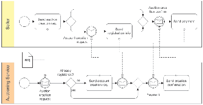
Consider, for instance, the simple example of a typical choreography model designed in BPMN shown in Figure 2. The BPD depicts the message flows between two partners, a seller and an auctioning service. The choreography describes the interactions needed for creating an auction. You see message send tasks and intermediate message events that are properly connected through message flow. Two pools are used. Control flow constructs are available to show the causal dependencies between the different communication actions; thus, the synchronization between both participants is a necessary behavioral property for successful collaboration.
The suitability and expressiveness of BPMN as a process modeling language has been explored from various perspectives [ 3, 4, 5, 6, 7, 11], however BPMN has not yet the semantic precision required to unambiguously represent fully executable BPs [ 12]. Moreover, in order to perform verification of critical properties of BPs, we first need to construct a formal model of the processes that are critical to the conduct of the business. The BP of interest must be modeled with the adequate formal notation, which is usually determined by the complexity of the communications carried out by the tasks in which the BP is structured. To obtain semantic precision and verifiability of syntactic constructs, in this work is suggests the use of TA theory as a formal description language for BP modelling languages.
3.2 Timed Automata (TA) and Model Checking (MC)
According to the TA theory, a timed automaton is a finite directed graph annotated with conditions over and resets of non–negative real valued clocks, and a system is modeled as a collection of finite state machines and a finite set of clocks. In the standard scheme the clocks are synchronized and can be reset by the transition from one state to another. Clocks are also used to guard transitions. Within TA, time is continuous but the clock’s statements are usually restricted to using integer values. Time is never negative as the clocks can only be resets to 0. Bounded liveness is represented by the requirement that some specific clock can never obtain a value greater than some specified deadline, or cannot do so while a state or collection of states is occupied. Transitions are defined to be instantaneous and hence it is possible to model behaviors that are not easily implementable. Where there are two or more possible transitions from a state then each is a valid transition.
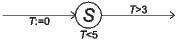
For example, according to the in Figure 3 the transition out of state  cannot be taken before time 3. In this example,
  is a clock; it is resetting when the state
  is achieve. In a simple model (i.e., the invariant
  do not exist) the only exit from the state
  is when
  is greater than 3; i.e., the example therefore illustrates the imposition of a delay. A state can also have a temporal invariant to force an exit transition. Figure 3 illustrate this because the state
  cannot leave before
  but must leave before
  . If for some reason the transition cannot be taken then the automata contains an error condition (deadlock).
Next are presented the basic definitions for timed automaton and TA–network, which are important for our purposes.
Definition 1 (Timed Automaton). A timed automaton is a tuple  that consists of the following components:
 is a finite set. The elements of
  are called the states of
  .
.  is a finite set called the alphabet or actions of
  .
.  is a finite set called the clocks of
  .
.  is a set of edges, called transitions of
  , where
  is the set of boolean clock constraints involving clocks from
  , and
, and  is the powerset of
  .
.
 is an element of
  , called the initial state.
An edge  is a transition from state
  to
to  with action
  , guard
  and clock resets
  .
.
As was introduced previously, the semantics of a timed automaton is defined as a transition system where a state or configuration consists of the current location and the current values of clocks. There are two types of transitions between states. The automaton may either delay for some time (a delay transition), or follow an enabled edge (an action transition). A timed action is a pair  , where
  is an action taken by a timed automaton
  after
after  time units since
  has been started. The absolute time
  is called a time–stamp of the action
  . A timed trace is a (possibly infinite) sequence of timed actions
  where
where  .
.
To model concurrent systems (as the BPs), TA can be extended with parallel composition. In process algebras, various parallel composition operators have been proposed to model different aspects of concurrency —see e.g. Calculus of Communicating Systems (CCS) [ 13] and Communicating Sequential Processes (CSP) [ 14]. These algebraic operators can be adopted in TA, which allows interleaving of actions as well as hand-shake synchronization. Essentially the parallel composition of a set of timed automaton is the product of the automata, just called TA–network.
Definition 2 (TA–network). A TA-network is the parallel composition 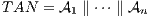 of a set of timed automata
  , called processes, combined into a single system by a parallel composition operator with all external actions hidden. Synchronous communication between the processes is by hand–shake synchronization using input and output actions. The action alphabet is assumed to consist of symbols for input actions denoted
  , output actions denoted
  , and internal actions represented by the distinct symbol
  .
.
TA are designed so that they can be verified by MC. In MC a formal model is checked for correctness against requirements expressed in temporal logic [ 1]. Intuitively, MC works by exploring all possible state transition from the initial state of the system. All possible traces from the beginning set of states are explored to see if an unsafe state can be reached or a liveliness condition broken. MC is a technique that requires tool support. In this work we use the Uppaal tool [ 8], because it supports the graphical representation of TA and allows the tool user to interact with a window editing program to create and modify models. In Uppaal, the product automaton is computed on-the-fly during verification. The tool also supports an interactive simulation facility which is a useful means of animating a model. A verify command invokes the model checker and allows requirement statements to be examined. If a required property is found to be false then a counter–example is generated and can be input to the simulator. From the business analysts and designers viewpoint, Uppaal is easy to use; although for non–trivial models considerable computing power is required by the model checker. The underlying formalism for Uppaal is TA–networks [ 8], which are easily understood by business people and faithfully reflect the BP–workers’ behavior in the BP execution. Currently the verification facility supports a slightly more expressive language then the simulator, very appreciated by those responsible for modelling BPs. As the use of the simulator is fundamental to the whole verification process we use only those features that the simulator implements.
3.3 Clocked Computation Tree Logic (CCTL)
Property specification languages are used to obtain a formal specification of the expected BP behavior according to the business requirements. CCTL [ 15, 16] is a propositional temporal logic that extends Computation Tree Logic (CTL) [ 1] with quantitative time bounds for expressing real time properties (e.g., bounded liveness). CCTL is used to deal with sequences of states, where a state gives a temporal interpretation of a set of atomic propositions (AP) at a certain time interval and time instants are isomorphic to the set of non–negative integers.
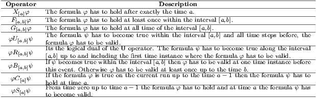
CCTL includes the CTL with the operators until (U) and next (X), and other derived operators in Linear Temporal Logic (LTL) [ 1], such as release (R), weak until (W), cancel (C) and since (S). In the Table 1 a textual description of some temporal operators usually deployed in CCTL specifications can be seen ( and
and  are arbitrary CCTL formulae, and
  and
and  are time bounds). All of them have proved to be useful for facilitating the definition of the properties included in reactive systems requirements specification. All LTL–like temporal operators are preceded by a run quantifier (A universal, E existential) which determines whether the temporal operator must be interpreted over one run (existential quantification) or over every run (universal quantification). See [ 15, 16] for more details.
Table 1: Informal description of some CCTL temporal operators.
Furthermore, all interval operators can also be accompanied by a single time–bound only. In this case the lower bound is set to zero by default. If no interval is specified, the lower bound is implicity set to zero and the upper bound is set to infinity. If the  –operator has no time bound, it is implicity set to one. For this paper we will only use the semantics for the
  and
and  –operators (“Always Globally” and “Eventually”, respectively), the semantics for the others operators may be found in [ 15, 16]. The semantics of CCTL is given be a model relation (
 ).
).
A business comprises several BPs. Under the BPMN approach, to entirely model a business is required one BPD by each BP. Each of these BPD represent a scenario where each BP–worker carry out the tasks scheduled in the BPs. In this work, and according to our experience, (1) each task is performed by only one BP–worker or automated system at time, and (2) is called BP–worker both the person that perform the task as the system that automates the task.
A BP–task model structure is a set of groups of tasks, representing a large number of possible real–world scenarios expressed in compact form. Thus, we are focused here on the BP–task model and the set of overlapping user scenarios, which allow us to obtain a description of most of the tasks that a BP–task model must take into account [ 17]. The compilation of all these scenarios constitute the BP behavioral view (see Figure 4); i.e., the BP–task model. Each BP–worker has a vision of a BP, according to their participation in the BP execution. When these partial behaviors are grouped, we obtain the BP–worker behavioral view. In this view, languages and formal techniques, such as finite state–machines or TAs, among others, have proved very useful to describe this behavior.
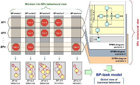
Due to a BP–worker can be concurrently involved in several BPs into a company, the BP–task model is obtained taking into account the behavior of these BP–worker according to each BP. The BP–worker are the ones who execute the tasks and are responsible of business behavior. Thus, the BP–task model gives us a cross–BP view of the business behavior, unlike the partial view showing by the BPDs. A BP–task model associated with a set of BPs combines the behaviors of every BP–worker involved in these BPs.
According to the approach described in this work, the complete description of the BP–task model behavior is obtained by a TA–network of a given set of BPs modeled with BPMN. Thus, some non–functional requirements (i.e., deadlock–freeness, reliability) and temporal constraints (i.e., timeliness, deadlines) that the BP–task model must fulfill are modeled by using a TA by each BP–worker or business entity. As result, we obtain a TA–network that specify and deal with behavioral aspects and temporal constraints of the BP–workers involved into the BP–task model. In this sense, the verification carried out here exclusively refers to the BP–task model behavior modeled by the TA–network that describe the behavior of the collaboration among BP–workers, i.e., the composition of the BP–workers execution.
Once obtained the TA–network, we can proceed to BP–task model verification by using the Uppaal [ 8] MC tool; i.e., it is possible to check whether a BP–task model satisfies the expected temporal behavior of the BP–task model specified with a set of CCTL formulas [ 15, 16]). These formulas comprise the formal specification of its properties representing the characteristics declaration of the BP–task model. Both execution and properties specification should be oriented by the associated BPs and business goals and rules. We obtain the verification of the BP–task model by the interpretation of boolean expressions (True, False), according to its expected behavior properties representing the expected characteristics declaration for the BP–task model.
We decided to use the Uppaal [ 8] MC tool, because is a tool box that allows us to model a BP–task model using TA, simulate it and the verify properties on it. In this sense, the features of Uppaal allow to any business analyst with the responsibility to define and model the BPs of a company, to study the temporal behavior of a BP using the TA–network representing a BP, in an easy and understandable way. The BP–worker’ interaction is pairwise and the result of this collaboration is used by one of the workers when it interacts with a new worker. Pairwise communication reflects the real world collaboration between distinct BP–workers, since it is carried out progressively by pairs. Otherwise this communication could not be represented clearly. With Uppaal, a BP–task model is modeled as a network of several synchronized TA in parallel, reflecting a sound reality of the interaction performed as part of the BPs.
5 Guidelines to transform BPMN to TA
The main contribution of this work is to propose a set of mappings and simple steps defined over the models to converts BPMN diagrams into TA–networks. This transformation is the first phase required to conduct the evaluation (i.e., qualitative analysis) of a BP. After, the TA–network generated by the transformation, which represents the BP–task model, is numerically analyzed by the support of a MC tool, as Uppaal, to provide varied business performance indicators (for instance, service time, waiting time or queue size) of a BP.
A BP consists of a set of coordinated activities that progress through an organizational and technical environment [ 18]. A BP is structured into a number of tasks that need to be performed by BP–workers or automated systems constrained to a set of business conditions and within a period of time that cannot be exceeded. A task is a atomic and logic unit of work that is completely carried out by a resource [ 19]. In these tasks, BP–workers participate by following a workflow (or process) that is defined by a given service. In addition, BPs are constrained by a set of business rules, which must be abided and determine the information structure and the policies of the company [ 20].
The process executes by a BP–worker passes through several states. For this work, these states, according to BPMN [ 2], can either be tasks, events or control gateways. These states are linked by sequence, exception or message flows, which represent the state transitions specified by the process. Sequence flows can be either incoming to or outgoing from a state and have associated guards. An exception flow from a state represents an occurrence of error within the state. Message flows represent directional communication between flow objects, which corresponds to the synchronization of separate processes. A sequence of sequence flow represents a specific control flow instance of the business process.
To transform BP models described by BPMN into TA–networks, the BP models are separated in three aspects: the behavior of each BP–worker, represented by a BPMN lane or by a pool without lanes in a BPD, the relations between the workers or departments, represented by BPMN diagrams or BPDs, and the time constraints on BPs, derived from the business rules. In few words, the two former are mapped onto time automaton and synchronization between timed automaton (i.e., to conform the corresponding TA–network), respectively, and the latter is mapped onto invariants, guards, and assignments on TA.
The behavior of a BP–worker (represented by a lane or by a pool without lanes in a BPD) is modeled as a states transition system or TA, which are characterized by their actions for channels synchronization, invariants, guards, and assignments. The next definition formalize the proposed mapping.
Definition 3 (BP–worker). A BP–worker modeled through a BPMN lane or pool without lanes, correspond to a timed automaton  that consists of the following components:
 is a finite set of BPMN flow objects; i.e.,
  . The elements of
  are called the states of
  .
.  is a finite set called the alphabet or actions (input and output) of
  , which is the synchronous communication between BP–workers.
  is a finite set called the clocks of
  .
.  is a set of edges, which correspond with both the BPMN sequence flow as the called transitions of
  , where
  is the set of boolean clock constraints involving clocks from
  , which represent the temporal constraints, and
  is the powerset of
  .
.
 is an element of
  , called the initial state, which correspond to the BPMN Start event.
An edge  is a transition from state
  to
to  with action
  , guard
  and clock resets
  .
.
The constant variables referred by invariants, guards, and assignments, are temporal parameters, the values of which are decided depending on the other aspects, i.e., the relations between the BP–workers and the constraints on the BP models. For instance, to specify the behavior of a BPMN tasks, the invariants ( ), guard conditions (
 ), and assignments or clocks resets (
 ) are defined on the locations and the edges of the corresponding timed automaton. Thus,
  is a clock variable that holds the elapsed time of task, and the invariant and the guard specify that the transition from task to any BPMN flow object (i.e., event, task, gateway) can never occur until the minimum execution time (
 ) has elapsed, and must occur before the maximum execution time (
 ) has elapsed. The constants variables (
 ,
,  ) are temporal parameters.
5.2 Synchronization of BP–workers
Each process carried out by one BP–worker into a company must interact with others BP–workers within the organization or with process from different organizations to perform completely a BP. Therefore, to obtain the formal representation of the BP–task model (see Figure 4), which describes how the BP–workers perform the tasks in terms of collaborating BP, the TA–network should be constructed. As result, we obtain a TA–network that specify and deal with behavioral aspects and temporal constraints of the BP–workers involved into the BP–task model.
Definition 4 (Synchronization of BP–workers). The synchronization of BP–workers is obtained as the parallel composition 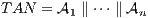 of a set of timed automata
  , called BP–workers, combined into a single system by a parallel composition operator with all external actions hidden. Synchronous communication between the workers/departments is by hand–shake synchronization using input and output actions. The action alphabet is assumed to consist of symbols for input actions denoted
  , output actions denoted
  , and internal actions represented by the distinct symbol
  .
.
5.3 Guide to conducting the transformation
According to our experience, transforming from annotated BPD onto TA can be achieved through the following steps:
- Include temporal constraints to BPMN diagram. For the verification of temporal properties of BPs, such as response time of business services, and temporal constraints, such as execution time of activities, should be specified in the BPDs. Due to there is no attribute for specifying these in BPMN, must be used the Intermediate event (timer) to define clocks and to incorporate temporal constraints on process flow. Note that an advantage of the approach proposed in this paper is not requires the use of some kind of temporal annotations or extension of BPMN, as proposed in Time–BPMN [ 5]. It is sufficient to use the timers or Intermediate events defined by BPMN, which are easy to use by business analysts.
- Obtain the timed automaton corresponding to each BP–worker. With reference to the definition 3 stated in section 5.1, the timed automaton required to specify the behavior of each worker is constructed to formally specify the workflow that the worker must be follow to collaborate in the execution of the BP.
- Assignment of values of constraints attributes on the annotated BPD to the corresponding variables on the timed automaton. According to the intermediate events added to the BPD, the invariants, guards, and assignments on the timed automaton are defined.
- Obtain the TA–network corresponding to the collaboration among BP–workers. From the definition 4 stated in section 5.2, the TA–network required to construct the BP–task model that specify and deal with behavioral aspects and temporal constraints of the BP–workers involved into the BP–task model. Assignment of channels to the timed automaton is according to the synchronization of BP–workers. It is also necessary to change the structure of the TA–network depending on the concurrency constraints.
As result of apply the above steps, the timed automaton (as the shown in Figure 7) is constructed and the TA–network (as the shown in Figure 8) is composed, in order to carry out the qualitative analysis of BPs in an easy way, at an adequate level of formality.
CRM is a strategy by which a company seeks to establish and maintain relations with its customers [ 21]. CRM is considered to be a complex combination of business and technical factors that should be aligned according to a strategy [ 21]. Briefly, the CRM’ BP modelling obtained the following BPs, Informing Customer, Customizing Service, Studying behavior Pattern, Product/Service Produce, Product/Service Sell and Assisting Customers, which represents a minimum functionality of the CRM strategy and are key factors to understanding the CRM business. As our objectives are not to show how the BP modelling was performed using BPMN, we will only use the BPMN diagrams considered of interest to show our entire verification approach.
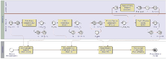
Is worth indicating that the CRM domain is wide a complex, but due to space limitations and the objectives of this research, to apply our proposal to the application example we shall mainly focus on verifying one part of the BP–task model associated with CRM. We opted to work with the Product/Service Sell and Product/Service Produce BPs, due to their importance to the CRM strategy. The information needed to perform the BP–task model verification is on the BPDs depicted on Figure 5 and Figure 6 that models the above BPs, and the business rules that the BP–task model must comply to meet the CRM business goals. Note that the BPDs depicted on Figures 5 and 6 have added timers, which corresponds to step 1 of the Guide to conducting the transformation presented in Section 5. In the next section these timers will be used to comply with step 3 of this guide and to obtain the CRM BP–task model.
Figure 5: BPD of the Product/Service Sell BP.
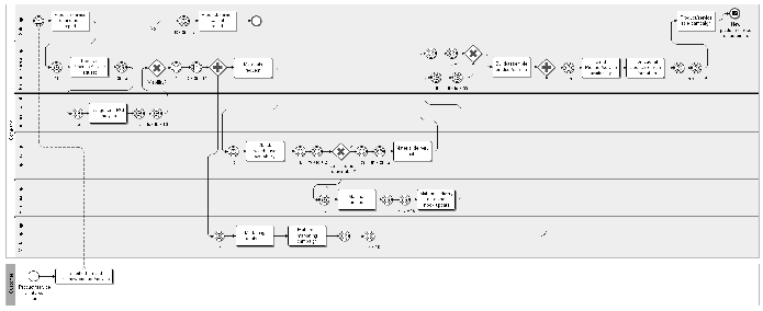
Figure 6: BPD of the Product/Service Produce BP.
For the purposes of this paper, let us observe that the Logistic worker is located in the execution of both Product/Service Sell BP and Product/Service Produce BP. This means that Logistic worker must to perform tasks associated with the Product/Service Produce BP with the responsibility of providing the materials required to create a new product/service. The Logistic worker also must to perform (collaboratively with the Attention Channel worker) the tasks associated with the Product/Service Sell when it receives a purchase order from a customer. In this sense, the Logistic worker should conform the time execution and synchronization established in the BP–task model associated to both BPs. Also, take into account that the Logistic worker should work collaboratively so closely with the Product/Service and Purchase workers to perform the Product/Service Produce BP. Hence, it must not be in conflict with other BP–workers as this could cause a deadlock (i.e., when it cannot perform any task) among a group of the BP–task model. In the software domain, deadlock means that all components are blocked (it cannot perform any computation) waiting for an event that is not possible.
We now proceed to model the BP–task model; i.e., the execution and synchronization of the BP–workers tasks implicated with the Product/Service Sell and Product/Service Produce BP–task model. To obtain this model, were applied the definitions 3 and 4 and followed the steps 2, 3, and 4, of the Guide to conducting the transformation presented in Section 5.
A TA was designed for each BP–worker (Customer, Sale, Attention Channel, Logistic, Product/Service, Purchase, Marketing, and Finances), using the definition 3 stated in section 5.1. For the sake of simplicity, next only is described the detailed behavior of the Logistic worker tasks (see Figure 7), which is considered to be the most important for the purposes of the present application, because he is concurrently involved in the execution of both BPs. The most important aspect of the Logistic worker execution is the transitions are modeled to accurately represent the possible execution of Logistic worker tasks; i.e., this worker can attend a request for a available product/service for the Attention Channel worker while it is waiting for the Purchase worker to acquire the materials that the Product/Service worker requires for build/assemble a new product/service.
TA in Figure 7 presents the states Consulting and Waiting, which are states entered by the Logistic worker when it is seeking information from the StockDB entity and collaborating with the Purchase worker, respectively. Note that this states correspond to the activities modeled in the BPDs depicted on Figure 5 and Figure 6. Additionally, the BusyA, BusyB, BusyC states were added to represent the situation when the Logistic worker is updating information in the StockDB entity, while the DispathA, DispatchB, and DispatchC states are reached when it is working with the Purchase worker. The Logistic worker is able to attend concurrently requests from the Product/Service Sell and Product/Service Produce BPs, respectively.
As can be seen in Figure 7, when the Logistic worker is in the IdleL state, concurrently requests from the Attention Channel and from Product/Service workers can both be attended. The Logistic worker leaves the IdleL state in the following cases:
- when it receives the Sen_disp_req event from the Attention Channel worker. In this case, the Logistic worker enters the BusyA state and captures the reception time of the request in the tw variable. It then sends the action Upd_ex to the StockDB entity. When it is in the BusyA state, the Logistic worker may not be able to receive Product/Service worker requests and remain in the current state while: (a) it is receiving from StockDB entity, within the time interval [tw,tw+2), the response Ex_upd and dispatching to the Attention Channel worker the task execution results (signal Disp_prod) and then passing to the IdleL state; or (b) it is in the waiting time for Ex_upd reception defeat; i.e., the time instant [tw+2,tw+2] is reached and a timeout is provoked, returning the Logistic worker to the IdleL state.
- when it is addressing the Mat_req from the Product/Service worker. In this case it passes to the Consulting state, storing in the td variable the time instant at which the request is received and initiates the execution of the action to satisfy it. This latter situation then presents two alternatives: (a) when the quantity of materials required is available (
 ) and the materials availability consulting event Show_aval is received the Logistic worker delivers the required results within the time interval [td,td+2), (signal Deliver) and again returns to the IdleL state; or (b) when the quantity of materials required is not available (
 ) and the materials availability consulting event Show_aval is received, the Logistic worker sends the material purchase request Purch_req to the Purchase worker and continues waiting within the [td,td+17) time interval to receive the notification of the material purchase.
Note that the temporal constraints discussed in the previous paragraph and assigned to the TA in Figure 7, corresponds to the timers previously placed in the BPDs depicted on Figures 5 and 6. This specification of invariants, guards, and assignments on the TA, corresponds to the execution of step 3 of the Guide to conducting the transformation presented in Section 5.
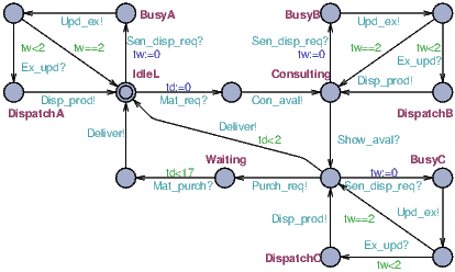
Having obtained the TA representing BP–workers, the definition 4 was applyed to mapping the synchronization among workers and accomplish with the step 4 of the Guide to conducting the transformation presented in Section 5. Figure 8 shows the simulator view of Uppaal, where are representing the TA–network conformed by the Logistic, Sale, Attention Channel, Product/Service, Purchase, Marketing and Finances workers and the StockBD entity, by means of their corresponding TAs. This is the result of applying the step 4 of the guide presented at the end of Section 5. We used this view to ‘simulate’ the CRM BP–task model execution to choose transitions to analyze, go through a trace (i.e., sequence of executed tasks), to see how certain states are reachable, and, finally, to analyze the CRM BP–task model behavior with respect to the CRM business indicators.
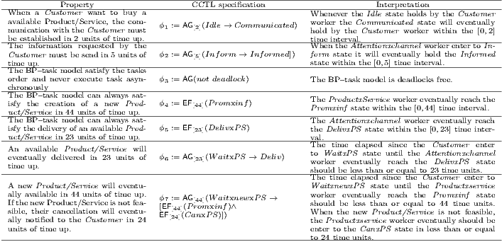
Taking into account the Product/Service Sell and Product/Service Produce BPDs and the abstract properties (i.e., business rules) previously set as the initial inputs to verify the BP–task model, we can now define what is expected to be accomplished by the CRM BP–worker when they receives a specific request from the Customer. Some of the expected behavior is specified by the CCTL formulas shown in Table 2, as an instance of the business rules according to the QoS contract level set by the CRM business.
Table 2: Some CRM properties – BP–task model expected behavior
The formulas in Table 2 describes the CRM BP–task model timed abstract behavior, which gives a high level of insight into what is expected of the CRM BP–worker to deliver when it receives a Customer request and how long would it take. On the other hand, these CCTL formulas specify the task order and the execution time required for each task (or set of task) expected from the Product/Service Sell and Product/Service Produce BP–task model to accomplish the BPs Quality of Service (QoS) contract level. In other words, with our approach we can checking two views of a business at the same time: the workers viewpoint and the processes flow viewpoint.
Note that the deadlock concept is being transferred from the software verification field to the BP world to obtain the  formula. Thus, we say that the BP–task model is deadlock–free if the CRM BP–workers are never blocked; i.e., a time deadlock–freeness reflects that the time constraints of the two composed BP–workers (i.e., two composed TA) are compatible. In other words, the BP–task model is deadlock–free because the tasks always are executed in order, which is the result of the correctness of the BP–workers synchronization. Thus, when we check that the BP–task model is deadlock–free, we are proved that the BP–task model satisfies tasks timely and orderly, i.e., the BP–workers do not perform tasks asynchronously.
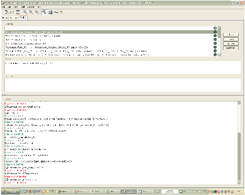
To proceed to the CRM BP–task model verification, we introduce each one of the CCTL formulas previously defined in section 6.2 in the Query field below Overview, using the Uppaal MC tool notation (see Figure 9). E.g., the Uppaal notation for the CCTL temporal formula ](/img/revistas/cleiej/v17n2/2a03102x.png) is E<>Product_service.Prom_inf imply ta<=44, and should be understood as “is it possible to reach the location Prom_inf in process Product_service in 44 units of time up”. The bullet in the overview section will turn green indicating that the property indeed is satisfied. Also appear in the status section the messages Property is satisfied or Property is not satisfied, below the text with the property checked, depending on the property pass or not the verification.
is E<>Product_service.Prom_inf imply ta<=44, and should be understood as “is it possible to reach the location Prom_inf in process Product_service in 44 units of time up”. The bullet in the overview section will turn green indicating that the property indeed is satisfied. Also appear in the status section the messages Property is satisfied or Property is not satisfied, below the text with the property checked, depending on the property pass or not the verification.
The most important result to highlight is that the BP–task model passes the verification of the property  ( A[](not deadlock) ), i.e., the BP–task model is deadlocks free, which means that the BP–task model does there occur a deadlock situation by which the BP–worker remain waiting indefinitely for communication between each other. Additionally, the BP–task model has satisfied the
  and
and  (see Table 2) properties verification, which means the BP–task model always met the Customer requests within the time stipulated by the QoS contract level for the Product/Service Sell and Product/Service Produce BPs, i.e., the BP–task model modeled completely satisfied the CRM business rules.
According to the results of the verification shown in Figure 9, we can say that the application of the approach support us to evaluate the behavior of the BP–task model with respect to business performance indicators (for instance, service time, waiting time or queue size) derived from business needs. We can assure that Logistic, Sale, Attention Channel, Product/Service, Purchase, Marketing and Finances workers and the StockBD entity, does not provoke a deterioration of the QoS required for the Product/Service Sell and Product/Service Produce BPs, respectively.
As described along the article, our verification approach is based on using the set of guidelines to transform BPMN to TA as main factor to ensure the proper construction of the BP–task model. Following the guide to conduct the transformation (presented in Section 5), the BP–task model of the application example was specified by a TA–network that faithfully reflects the behavior of the BP–workers that are composed in parallel. As we can see in this application example, the proposed approach to perform the verification activity and the mapping definitions 3 and 4 ensures the preservation of the individual properties associated with independent task–sets within the BP–task model into which they are integrated; i.e., the resulting BP–task model (modeled as a TA–network) can be used to conduct qualitative analysis (validation and verification).
The main contribution of this work is to propose a set of mappings and simple steps defined over the models to converts BPMN diagrams into TA–networks. This transformation is the first phase required to conduct the evaluation (i.e., qualitative analysis) of a BP. Also, we describe how MC verification technique for software and TA formal language are integrated within a formal verification approach to check BPs modeled with BPMN. Along the paper has shown that is methodologically feasible providing support to BP analysts and designers to conduct the qualitative analysis of a BP–task model associated to a BPMN diagram using the TA theory. Our proposal was applied to a real project related to the CRM business modeled with BPMN and verified with the Uppaal MC tool.
Future work is aimed on the formalization of the guidelines introduced in this paper as a set of transformation rules that can be automated and incorporated in our BTransformer[ 22] tool (developed using Open Unified Process (OpenUP) methodology, http://www.eclipse.org, BTransformer has the capability to read input/output models written in standard XML and it can be used with different operating systems: Windows, Linux and MacOS; the idea is to construct a new version of this tool to generate the TA from any source BPMN diagram by the access to a future BPMN2TA menu option). With this version of BTransformer, we can automate the support to business analysts to obtain “as–equivalent–as–possible” executable BP–task models in TA that ensures the proper evaluation (i.e., qualitative analysis) of BPs modeled with BPMN using the Uppaal MC tool.
This research was partially supported by National Fund of Science, Technology and Innovation, Venezuela, under contract G–2005000165 and conducted as part of the Information Systems Research Laboratory (LISI, by the Spanish acronym Laboratorio de Investigación en Sistemas de Información) research group.
[1] E. Clarke, O. Grumberg, and D. Peled, Model Checking, ser. MIT. Cambridge, USA: The MIT Press, 2000.
[2] OMG, Business Process Model and Notation – v2.0. Massachusetts, USA: Object Management Group, 2011. [Online]. Available: http://www.omg.org/spec/BPMN/2.0/PDF
[3] S. Morimoto, A Survey of Formal Verification for Business Process Modeling, Lecture Notes in Computer Science 5102: Proc. 8th International Conference on Computational Science (ICCS 2008). Berlin: Springer–Verlag, 2008, pp. 514–522.
[4] P. Wong and J. Gibbons, “A relative timed semantics for {BPMN},” Electronic Notes in Theoretical Computer Science, vol. 229, no. 2, pp. 59–75, 2009.
[5] D. Gagne and A. Trudel, “Time–bpmn,” in 2009 IEEE Conference on Commerce and Enterprise Computing (CEC 2009). Los Alamitos, USA: IEEE Computer Society, 2009, pp. 361–367.
[6] L. Mendoza, M. Capel, and M. Pérez, “Conceptual framework for business processes compositional verification,” Information and Software Technology, vol. 54, no. 2, pp. 149–161, 2012.
[7] L. Mendoza, “Business process verification using a formal compositional approach and timed automata,” in XXXIX Conferencia Latinoamericana en Informática (CLEI 2013). Los Alamitos, USA: IEEE Computer Society, 2013, p. To appear.
[8] G. Behrmann, A. David, and K. Larsen, “A tutorial on uppaal,” in Formal Methods for the Design of Real-Time Systems: 4th International School on Formal Methods for the Design of Computer, Communication, and Software Systems, SFM-RT 2004, ser. LNCS, M. Bernardo and F. Corradini, Eds., no. 3185. Springer–Verlag, September 2004, pp. 200–236.
[9] M. Capel, L. Mendoza, and K. Benghazi, “Automatic verification of business process integrity,” Int. J. Simulation and Process Modelling, vol. 4, no. 3/4, pp. 167–182, 2008.
[10] K. Watahiki, F. Ishikawa, and K. Hiraishi, “Formal verification of business processes with temporal and resource constraints,” in 2011 IEEE International Conference on Systems, Man, and Cybernetics (SMC 2011). Los Alamitos, USA: IEEE Computer Society, 2011, pp. 1173–1180.
[11] C. Combi and R. Posenato, “Controllability in temporal conceptual workflow schemata,” in Business Process Management, ser. Lecture Notes in Computer Science. Springer Berlin / Heidelberg, 2009, vol. 5701, pp. 64–79.
[12] K. Greer, Thinking Networks - the Large and Small of it: Autonomic and Reasoning Processes for Information. CreateSpace Independent Publishing Platform, 2008.
[13] R. Milner, A Calculus of Communicating Systems. Secaucus, USA: Springer–Verlag New York, Inc., 1982.
[14] C. Hoare, Communicating Sequential Processes, ser. International Series in Computer Science. Hertfordshire UK: Prentice–Hall International Ltd., 1985.
[15] J. Rüf and T. Kropf, “Symbolic model checking for a discrete clocked temporal logic with intervals,” in Proceedings of the IFIP WG 10.5 International Conference on Correct Hardware Design and Verification Methods. London, UK: Chapman & Hall, Ltd., 1997, pp. 146–163.
[16] ——, Modeling and checking networks of communicating real–time processes, Lecture Notes in Computer Science 1703: Correct Hardware Design and Verification Methods (CHARME). Berlin: Springer–Verlag, 1999, pp. 256–279.
[17] F. Paternò, Handbook of Software Engineering And Knowledge Engineering: Recent Advances. River Edge, USA: World Scientific Publishing Co., Inc., 2001, ch. Task Models in Interactive Software Systems.
[18] M. Weske, Business Process Management: Concepts, Languages, Architectures. Berlin, Germany: Springer Berlin Heidelberg, 2007.
[19] W. Aalst and H. Kee, Workflow Management: Models, Methods, and Systems, ser. Cooperative Information Systems. Cambridge, USA: MIT Press, 2004.
[20] M. Ortín, J. García, B. Moros, and J. Nicolás, “El modelo de negocio como base del modelo de requisitos,” in Actas de las Jornadas. de Ingeniería de Requisitos Aplicada, Sevilla, Spain, 2009.
[21] L. Mendoza, A. Marius, M. Pérez, and A. Grimán, “Critical success factors for a customer relationship management strategy,” Inf. Softw. Technol., vol. 49, no. 8, pp. 913–945, 2007.
[22] A. González, L. Mendoza, M. Capel, M. Pérez, A. Méndez, and K. Domínguez, “BTransformer – a tool for BPMN to CSP+T transformation,” in Proc. 13th International Conference on Enterprise Information Systems (ICEIS 2011), vol. 3. Setúbal, Portugal: SciTePress, 2011, pp. 363–366.
 Todo el contenido de esta revista, excepto dónde está identificado, está bajo una Licencia Creative Commons
Montevideo - Uruguay.
Tel: (598) 2711 4244 int. 124

CLEIejEditor@fing.edu.uy