


Servicios Personalizados
Revista

Articulo
 Inglés (pdf)
 Articulo en XML
 Referencias del artículo
Links relacionados
Compartir

 Permalink
CLEI Electronic Journal
versión On-line ISSN 0717-5000
CLEIej vol.16 no.3 Montevideo dic. 2013
Abstract
The use of directional antennas in support of ad hoc networks has been considered a promising alternative to improve spatial division multiple access and throughput. In general, directional Medium Access Control (MAC) protocols are based on IEEE 802.11 standard, which was designed for omnidirectional communication. When applied to directional communication, the standard imposes a number of constraints to the directional MAC protocol. In order to harvest the benefits of directional communications, MAC protocols tailored for directional antennas have to be devised. In particular, MAC protocols that are able to deal with deafness and channel reservation latency are highly desirable. This work proposes a technique that enables channel reservation and mitigates deafness using pulse/tone signals in the context of directional communications. At its heart, the proposed technique incorporates a deafness predictions scheme that helps nodes to overcome its effects. Analytical results show that the proposed technique is able to improve throughput up to 40% when compared to other prominent directional MAC protocols. Simulation results show that the proposed scheme improves fairness and throughput up to 350% and 76%, respectively.
Portuguese abstract:
O uso de antenas direcionais em redes ad hoc tem sido considerado uma proeminente alternativa para prover melhorias ao reuso do espaço aéreo e à vazão. Em geral, os protocolos MAC direcionais se baseiam no padrão IEEE 802.11 que por sua vez foi projetado à luz de comunicações omnidirecionais. Quando aplicado às comunicações direcionais, o padrão impõe uma série de limitações aos protocolos MAC direcionais. Para melhor aproveitar os benefícios das comunicações direcionais, faz-se necessário o desenvolvimento de protocolos projetados levando em consideração as características das antenas direcionais. Em particular, é desejável que estes protocolos MAC sejam capazes de amenizar o problema de surdez de antenas, bem como a latência imposta pela reserva de canal. Este trabalho propõe uma técnica que possibilita a reserva de canal por meio de sinais pulse/tone, atenuando ainda os efeitos do problema de surdez de antenas. A técnica proposta incorpora um mecanismo de predição de surdez que auxilia os nós a superar os efeitos do problema. Os resultados teóricos mostram que a técnica proposta é capaz de prover ganho de até 40
Keywords: Distributed Systems and Networks, Directional Communications, Channel Reservation, Deafness Problem, Receiver-initiated Communications, Pulse/Tone.
Portuguese keywords: Redes e Sistemas Distribuídos, Comunicações Direcionais, Reserva de Canal, Problema de Surdez de Antenas, Comunicações iniciadas pelo receptor, Pulso/Tom
Received: 2013-03-01, Revised: 2013-11-05 Accepted: 2013-11-05
Nodes in a wireless network usually share a common, unlicensed, communicating channel. Such channels are generally borrowed from the ISM (Industrial, Scientific, and Medical) bands, which are free for non-commercial use. The IEEE 802.11 standard is perhaps the most successful example [ 1]. The IEEE 802.11 describes the operations of the data link, Medium Access Control sublayer (MAC), and physical layers of a wireless local area network. The channel reservation mechanism employed by the IEEE 802.11 MAC sublayer has been the focus of several studies [ 2] [ 3]. The main task of a MAC protocol is to allow multiple nodes to communicate in an efficient way [ 4]. According to [ 5], the efficiency of a MAC protocol can be characterized as being proportional to the amount of successful transmissions. Traditionally, studies related to wireless networks assume that the devices are empowered with omnidirectional antennas [ 6]. To avoid DATA frame collisions, and hence improve throughput, most medium access control mechanism performs channel reservation based on control frames, such as RTS/CTS (Request to Send/Clear to Send) frames [ 1]. Despite its benefits, channel reservation based on control frames also imposes severe constraints in terms of spatial reuse, once the nodes overhearing these frames are not allowed to communicate. These constraints have a direct impact on network throughput and delay [ 2] [ 3]. In order to improve network performance, alternatives such as packet aggregation schemes have been explored [ 7]. Another possibility to improve spatial division is to equip mobile devices with a directional antenna [ 8]. A directional antenna has the ability to direct its beam towards the intended source/destination. The direction is selected such that the signal strength is maximized [ 5]. Some of the main advantages of directional antennas use are interference reduction; higher transmission range; better signal quality; and improvement on spatial reuse. In order to better profit these advantages, directional MAC protocols should be able to explore these features in a positive way.
As described by references [ 9] [ 10] [ 11] [ 12], the development of an efficient directional MAC protocol is not trivial due to directional hidden and directional exposed terminal problems. On top of that, directional communications also suffer from “deafness” problem [ 11]. As the directional antennas are typically half-duplex, when a node points its antenna direction towards a particular sector/direction, the signals arriving from other sectors/directions are not captured. It is important to state that both deafness and directional hidden terminal problem have no solution for a model that considers single radio and single channel [ 13]. More precisely, the deafness problem may cause several packet losses which impacts on network delay and throughput [ 14]. In some specific cases, the deafness problem may lead even to deadlock situations [ 15].
In this context, this work proposes a deafness mitigation technique that explores the use of pulse/tone signals in replacement to the RTS/CTS frames of the IEEE 802.11. Pulse and tone signals can be sent and received in a fraction of the time spent with RTS/CTS control frames. For this reason, pulse and tone signals have been explored in the literature in different contexts, such as channel reservation and to avoid control frame collisions [ 14] [ 16] [ 17]. The proposed scheme, termed Directional Pulse/Tone Based Channel Reservation With Deafness Avoidance (DPTCR-DA), presents a novel channel reservation and deafness avoidance scheme. At its core, the DPTCR-DA is able to efficiently employ pulse and tone signals to replace the expensive RTS/CTS frames for channel reservation purposes. Using pulse and tone signals, a receiver initiated scheme is devised to reduce the deafness impact on directional communications. Analytical results show that the proposed technique is able to improve throughput up to 40% when compared to other prominent directional MAC protocols. Aiming to evaluate the proposed technique, it was held several simulations on the EXata Simulator [ 18]. These simulations results have shown that the DPTCR-DA is able to improve throughput and fairness while reducing jitter effects. More precisely, the DPTCR-DA improved fairness and throughput up to 350% and 76% respectively, as compared with similar strategies.
The rest of this document is organized as follows: Section 2 presents IEEE 802.11 standard characteristics which are closely related to the scope of this work. This section also presents a review of directional communications, deafness problem and existing directional MAC protocols. Section 3 describes the proposed deafness alleviation technique along with an example of its operation. Section 4 presents the evaluated scenarios, simulation environment, theoretical and empirical results. Finally, Section 5 presents the conclusions of this work and points some directions for further investigations.
This section presents the IEEE 802.11 standard [ 1], as well as motivation, advantages and problems of the use of directional communications. Also, it presents an explanation of the deafness problem and related works in what concerns to directional MAC protocols.
The building blocks provided by the IEEE 802.11 [ 1] standard has been used in many directional MAC mechanisms, such as [ 9] [ 19] [ 20]. In this section, we review some key elements of the IEEE 802.11 standard that are closely related to this work. These elements are the following:
- Channel Reservation;
- Virtual Carrier Sensing;
- Backoff.
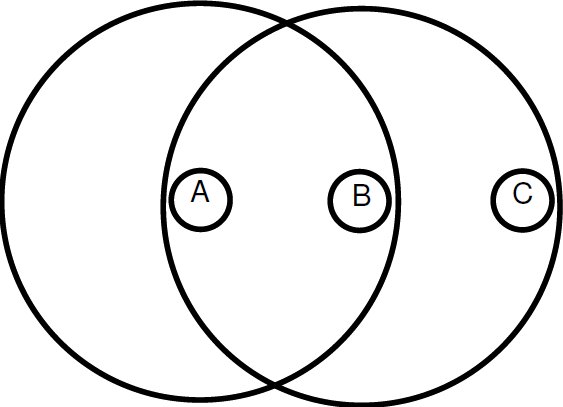
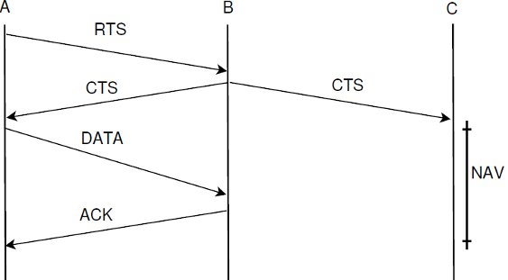
In the IEEE 802.11, channel reservation based on RTS/CTS frames is optional and aims to minimize losses due to data packets collisions. This technique consists of an attempt to reserve the channel before sending DATA frames in order to avoid collisions. Control frames include, among other information, the source and duration of the intended communication. Neighboring nodes overhearing the RTS and/or the CTS, postpone their transmission until the “duration” (this refers to the value of the duration field contained in a received RTS/CTS frame) time is elapsed. Consider the network topology shown in Figure 1. Suppose that nodes A and B wish to communicate. Then, as shown in Figure 1, DATA and ACK frames follow the successful exchange of RTS and CTS frames. The use of RTS/CTS, DATA/ACK frames is commonly termed as 4-way handshake.
The use of RTS/CTS in directional communication has been first considered in [ 9] [ 19]. In directional environments, these control frames can be sent either in directional or in omnidirectional mode, depending on the neighboring information available [ 21]. When using only directional communications, directional RTS (DRTS) and directional CTS (DCTS), directional hidden terminal and deafness problems may arise, which have no solution for a model that considers single radio and single channel [ 13].
However, a successful DRTS/DCTS (or RTS/CTS) exchange minimizes data frame collisions. Nevertheless, control frame collision can still occur. The RCA protocol [ 16] uses pulse/tone signals to avoid control frame collisions. As RTS/CTS frames have a considerable impact on network throughput, the RCA uses a 6-way handshake (pulse-tone-RTS-CTS-DATA-ACK) in order to decrease the amount of control frame collisions [ 16]. A directional version of RCA was proposed in [ 20]. On the other hand, this proposal further increases network latency. In [ 22], we proposed a technique to reduce latency by using pulse/tone signals instead of RTS/CTS frames. The benefit of the proposed scheme is that it maintains RTS/CTS features, since it also minimizes data frame collisions. This paper proposes an extension of our previous work, which explores pulse/tone signals to mitigate the deafness problem.
The IEEE 802.11 allows a host to verify the status of medium in two different ways: physical or virtual carrier-sense. When the channel state is sensed busy by either mechanism, the channel is considered busy and, otherwise, idle. Physical carrier sensing is a costly operation in terms of power consumption [ 23]. Also, physical carrier sensing may not provide information regarding the amount of time an ongoing communication will last. As explained above, the RTS/CTS have information about the duration time of the communication. Thus, a neighboring node overhearing an RTS/CTS frame sets the channel as busy for the duration contained in the control frames, as node C does in Figure 1. This feature is implemented via the Network Allocation Vector (NAV). The NAV has a counter that represents the remaining time of the current communication. When the NAV is not set, the physical carrier sense is then used to ensure that the channel is idle.
The use of directional virtual carrier sensing (DVCS) was proposed by [ 19]. For this, DVCS as well as DMAC (Directional MAC Protocol) [ 9] uses DNAV structure which is a directional version of NAV. The main difference between DVCS and DMAC is that the first one is able to operate with both directional and omnidirectional antennas. A number of directional MAC protocols in the literature use the DVCS and inherit some of the IEEE 802.11 standard characteristics [ 6].
As IEEE 802.11 standard uses CSMA/CA MAC protocol, it inherits its exponential backoff [ 1]. Exponential backoff aims to minimize frame collision probability by forcing every node to choose a number ( ) in the range [0,
  ], where CW denotes contention window. After
  idle slots (a slot is considered to last
  [ 1]), the node is able to engage in communication. If this packet collides, the CW (contention window) is doubled in a way that a further collision has a lower probability to occur since the chosen number will be now in the range [0,
  ]. The next subsection presents the motivations, advantages and problems of directional communications.
2.2 Directional Communications
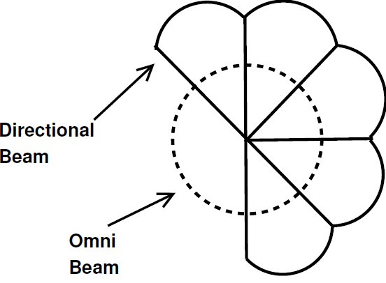
Owing to its beamforming capability of concentrating energy towards a given sector, a directional antenna presents several advantages over omnidirectional counterparts, particularly in terms of spatial reuse [ 5] [ 6] [ 9]. This feature minimizes interferences and allows for increasing transmission range. In this work, it is considered the use of switched beam antenna (Figure 2) with characteristics similar to those described in [ 21]. A switched beam antenna consists of dividing the antenna in  sectors, where each one covers an angle equal to
  . Switched beam antennas are expected to be produced at a much lower cost, while being able to provide most of the benefits of a more sophisticated system [ 11]. Hence, switched beam antennas seems to be a feasible option as a first generation technology to be used in ad hoc networks. It is important to state that switched beam antennas use is assumed in a number of related works [ 5] [ 6] [ 9] [ 20]. Although the technique proposed in this work is able to operate with other antenna types, it was assumed the use of switched beam antennas due to the aforementioned reasons. In particular, it is assumed that the receiver, empowered with a directional antenna, is capable of estimating the angle of arrival (AOA) and received signal strength (RSSI) of an incoming signal. Also, a directional antenna is able to operate either in omnidirectional or in directional mode. This work assumes that directional and omnidirectional beam have the same transmission range, which can be accomplished by reducing the transmission power when operating in directional mode [ 5].
As mentioned in Section 1, the utilization of directional antennas also imposes some limitations to the network, as the well known deafness problem. Such limitations will be discussed in the next subsection.
In general, a directional antenna is usually considered to be half-duplex. As described in [ 15], a node that uses a directional antenna is considered “deaf” in all other directions except the one it is beamformed. This problem was identified by [ 9].
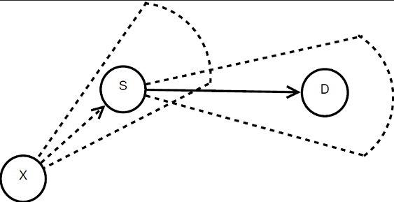
Consider the scenario illustrated in Figure 3, where all transmissions occur in directional mode. In the figure, node  wants to communicate with node
  . However, node
  is beamforming towards
  because of an ongoing communication. Thus, node
  is “deaf” to
  in this moment. In this case, it is said that the node
  and the flow
  are suffering from deafness. The presented situation causes a diminishment of throughput and an increase of the transmission time for each packet that
  tries to transmit to
  . When deafness problem occurs frequently for the same node, this situation is called persistent deafness [ 24].
Deafness problem has a direct impact on the network performance, leading to higher delay time, unfair assignment of network resources, increase of backoff window and even specific situations of deadlock [ 14] [ 15]. So, the need of mitigating the consequences of deafness problem has become paramount. Indeed, some of existing directional MAC protocols developed mechanisms which aim to perform this task. In what follows we review some directional MAC protocols and techniques which are closely related to this work.
2.3 Existing Directional MAC protocols
One of the earliest and important technique related to directional communications is the DVCS (Directional Virtual Carrier Sensing – 2002) [ 19]. This technique of carrier sensing evokes a directional version of NAV (DNAV). DVCS also supports interoperability between devices that operate with omnidirectional and directional antennas. It is important to state that DVCS is a technique instead of a protocol. In this sense, the DVCS can be coupled to different MAC protocols. When DVCS was proposed [ 19], it was coupled to the IEEE 802.11. In this work we consider that the DVCS is coupled to IEEE 802.11 standard. In the meantime, DMAC (Directional MAC protocol – 2002) [ 9] arose. This protocol proposed that the frames RTS/CTS, DATA/ACK should be sent only in directional mode, which makes the DMAC to suffer from deafness problem. In order to mitigate the latency introduced due to deafness, ToneDMAC (Tone Directional MAC – 2005) [ 14] resorted to the use of pulse/tone signals (sent in omnidirectional mode) in a control channel. However, this protocol did not address fairness. In turn, RI-DMAC (Receiver Initiated Directional MAC – 2006) [ 24] proposed the use of receiver initiated communications with the frame RTR coupled to a deafness prediction mechanism, which is based on next packet information. Although RI-DMAC achieves fairness improvements in certain conditions, it also fails when the packets being sent are not in sequence. In other words, RI-DMAC is not able to improve fairness in scenarios where alternate flows originate from a node having its backoff window growing due to deafness.
The CW-DMAC (Control Window Directional MAC – 2010) [ 13] proposes the use of RTS/CTS frames in omnidirectional mode, including in these frames information about the sector that will be used for that communication. This protocol does not address fairness, but it reduces the unnecessary backoff window increase due to deafness. The DC-DMAC (Dual Channel Directional MAC – 2010) [ 11] also proposed the use of RTS/CTS in omnidirectional mode (in a control channel). This protocol relies on a geometric concept based on the antenna range to identify deafness occurrence in many cases. In this way, DC-DMAC is able to reduce the losses caused by deafness. However, this protocol does not provide a fair assignment of network resources. The DVCS-DA (Directional Virtual Carrier Sensing with Deafness Avoidance – 2012) [ 25] resorts to receiver initiated communications with the RTR frame combined to a traffic flow oriented deafness prediction mechanism. Unlike RI-DMAC, the DVCS-DA is able to provide fair use of the network resources, even in cases where the next packet information fails. Table 1 shows a summary of what was discussed above.
This paper proposes a deafness mitigation technique, termed Directional Pulse/Tone Based Channel Reservation with Deafness Avoidance (DPTCR-DA). The DPTCR-DA uses receiver initiated communications with tone signal coupled to a deafness prediction mechanism. Also, DPTCR-DA evokes the use of pulse/tone signals in an innovative way to perform channel reservation in both operation modes (sender initiated and receiver initiated), thus reducing network latency.
![-------------------------------------------------------- Protocol/ Control RTS/CTS Another -Technique--------Channel------Mode--------frames/signals-- -DVCS--[19]---------No-------Directional---------No------- -DMAC---[9]---------No-------Directional---------No------- -ToneDMAC---[14]----Yes------Directional--------Tone------ -RI-DMAC--[24]-----No-------Directional--------RTR------- -CW--DMAC--[13]----No-----Omnidirectional-------No------- -DC--DMAC---[11]-----Yes----Omnidirectional-------No------- -DVCS--DA-[25]-----No-------Directional--------RTR------- -DPTCR----DA-------No------Directional----Pulse/Tone----](/img/revistas/cleiej/v16n3/3a0117x.png)
3 DPTCR-DA: Directional Pulse/Tone Based Channel Reservation with Deafness Avoidance
This section presents the details of the proposed deafness mitigation technique, named Directional Pulse/Tone Based Channel Reservation with Deafness Avoidance (DPTCR-DA). The DPTCR-DA relies on a channel reservation scheme based on pulse/tone signals instead of RTS/CTS frames. This channel reservation scheme is an extension of our previous work [ 22] and allows for significant throughput improvement as pulse/tone signals are much shorter than RTS/CTS frames. The channel reservation technique proposed has a negligible probability of failure when the antenna model is able to measure the angle of arrival (AOA) and the received signal strength indicator (RSSI) under reasonable accuracy [ 22].
Furthermore, DPTCR-DA uses a deafness prediction mechanism to decide whether a node will try to begin a receiver initiated communication using a tone signal. The referred mechanism is based on local traffic flow information, in a similar way to the used by DVCS-DA [ 25]. Pulse/tone signal based channel reservation, and the deafness prediction mechanism will be presented next.
3.1 Channel Reservation Using Pulse/Tone Signals
The use of pulse/tone signals in omnidirectional mode has been considered in [ 14] [ 17] to avoid hidden terminal problems in omnidirectional communications. Besides, pulse/tone signals have been explored in the context of directional antennas [ 20]. For this kind of environment, pulse/tone signals can be used in order to reduce the overhead introduced by RTS/CTS control frames. Precisely, the proposed scheme uses pulse and tone signals instead of RTS/CTS frames. It is assumed that pulse and tone signals are transmitted in-band using a single channel and single radio model. Also, it is assumed that pulse and tone signals can be transmitted and detected in less than  , as in [ 16] [ 20].
Recall that RTS/CTS frames allow the receiver to identify if the incoming frame is destined for it or not. The main challenge when using pulse and tone signals is to provide means to identify the transmitter/receiver, as well as to estimate the duration of the communication, in order to update DNAV properly. As pulse/tone signals carry no information, ways to identify the transmitter, receiver and duration of the communication need to be devised. Means to deal with the above challenges are presented in the subsequent sections.
3.1.1 Pulse/Tone Based Channel Reservation: An Example
Channel reservation using pulse/tone signals is similar to the IEEE 802.11 standard coupled with DVCS [ 19]. Therefore, channel reservation using pulse/tone signals also uses a 4-way handshake as the example illustrated in Figure 3. In this example, it is assumed that node  has a DATA frame to send to node
  . Following the IEEE 802.11, the transmitting node
  waits its backoff time and then tries to initiate a communication by sending a pulse signal in directional mode to
  . Assume that node
  is able to identify the source node and the duration of the intended communication from the received pulse. Then, node
  checks if it is able to send the tone back to
  , that is, if the direction toward
  is available. Using a similar approach, node
  replies with a tone signal in directional mode to
  . After a successful exchange of pulse/tone signals, DATA/ACK frames are exchanged. Clearly, for the above scenario to work properly, ways to estimate the source and destination node, as well as to predict the communication duration are needed. In what follows, we discuss how such information can be obtained from the pulse/tone exchange.
3.1.2 Estimation of Duration, Source and Destination from a Pulse/Tone
The mechanism which predicts the signal source, destination and duration constitutes an important piece of channel reservation using pulse/tone signals technique, since it allows to perform the channel reservation relying on physic layer signals instead of MAC layer frames. In ad hoc settings, each node needs to acquire knowledge about its vicinity [ 6]. To accomplish this, broadcast messages are issued at regular intervals. Therefore, it is not hard for each node to store in its routing table the Received Signal Strength (RSSI) and Angle of Arrival (AOA) information of its neighbors [ 19]. The proposed mechanism makes the channel reservation using physical layer signals possible as AOA assists to estimate the direction of the incoming signal, while RSSI assists to estimate the distance to the transmitter. Also, this mechanism assumes that the antenna is able to manage its energy in a way that its transmission power be proportional to the distance of the destination node. When receiving a signal, the receiver can check the AOA and RSSI on its routing table to infer the transmitter’s ID, thus identifying the signal source. Due to the antenna transmission power management, if the RSSI is high, it means that this signal is not bound for the current node, thus allowing the identification of signal destination. Therefore, the proposed mechanism performs channel reservation in the same cases as DVCS does. It will be shown that the failure probability of the proposed scheme is negligible.
In which concerns to duration, channel reservation using pulse/tone signals requires that 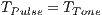 is proportional to base 2 logarithm of the data packet size that will be transmitted. The duration time
  is such as:
  , where
  is the payload size of data packet to be transmitted and
  denotes pulse/tone detection time. Any node that overhear a pulse or a tone signal can update its DNAV properly, since the proposed technique limits the possible packet size as follows: Every packet has size
  ,
,  or equal to
  . This limitation of
  bytes is due to the MTU (Maximum Transmission Unit) of the Ethernet standard (IEEE 802.3) be equal to
  or to
or to  (Ethernet Version 2), since in general it is assumed the use of Ethernet. Using AOA and RSSI information, the presented scheme attains the same behavior as when DRTS/DCTS are used. The proposed technique dramatically reduces channel reservation latency, once pulse and tone signals are transmitted in a fraction of the DRTS/DCTS time.
From the above discussion, it is clear that the goodness of the proposed mechanism is associated with the accuracy of the AOA and RSSI. This issues are discussed in the subsequent section.
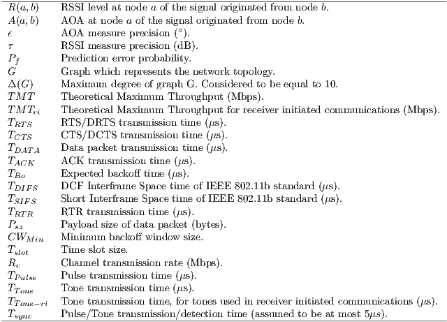
The goal of this subsection is to show that, under reasonable AOA and RSSI accuracy, prediction errors are negligible. For the convenience of the readers, the major notations used in this subsection are listed in Table 2. Suppose, without loss of generality, that node  has at least two neighbors
  and
and  , such that:

In the case where Inequalities 1 and 2 occur, the signal source prediction mechanism of  may predict the wrong source, since it cannot distinguish a pulse or tone signal incoming from
  or
or  in this case. Note that this prediction error conditions can occur for more than two nodes at the same time. The presented analysis addresses this case by considering all pairs of
  ’s neighbors as candidates to be
  and
and  . Therefore,
  is defined as follows:

Due to the two events described in Inequality 3 be assumed as independent, we have:

Hence, by considering the Two-Ray channel propagation loss and using the parameters described in Table 3, it was possible to compute the prediction error probability ( ) for various values of
  and
and  , as described in [ 22]. Table 4 displays the calculated
  values. By observing Table 4, one can notice that
  has a low prediction error probability for all considered RSSI and AOA accuracy values. It is important to state that the RSSI precision has been reported to be as lows as
  dB [ 12]. According to [ 26] [ 27], the AOA estimation can achieve a precision better than
  for the antenna model considered in this paper. In this case (
 ,
,  ),
),  has an almost negligible error probability, less than
  . It should be noted that in the presented
  calculus, it is considered that
  is a regular graph of degree
  what tends to increase
  smoothly. Thus,
  value is still lower than the presented in Table 4, which is already an almost negligible probability. These considerations end the presentation of channel reservation using pulse/tone signals. Next, it will be presented the deafness prediction mechanism, which is responsible for triggering receiver initiated communications, thus mitigating losses due to deafness.
 calculation
 for various values of
  and
and 
3.2 Deafness Prediction Mechanism
The deafness prediction mechanism plays an important role for DPTCR-DA. It determines which flow is suffering from deafness problem for longer time, if there is any. In other words, it is verified which neighbor is waiting for more time to send a data frame. So, deafness prediction depends on the instant of reception of the last frame, and the deafness threshold ( ) for each flow
  , where
  denotes the flow index. For example, a node performs deafness prediction verifying
  for each flow
  incident to that node, where
  denotes the waited time for the flow
  . A flow is predicted as suffering from deafness if the waited time (
 ) is higher than the deafness threshold (
 ), in other words, if
  .
.
It is important to state that the deafness threshold is a function that depends on the expected interval between packets ( ). Deafness threshold can be defined as:
  , where
  is an estimated factor. For each flow
  ,
,  can be based on the information contained in the active flow table. Other possible ways to perform this estimation are described by [ 25].
As other protocols that use receiver initiated communications, the proposed technique (DPTCR-DA) has two operation modes (depicted in Figure 4), namely:
- Standard Mode: used in when deafness is not forecast. This mode uses sender initiated communications, in a similar way to the one exemplified in Figure 4. In this mode, DPTCR-DA relies on the use of pulse/tone signals instead of frames to perform channel reservation [ 22]. Using the results of the previous section, channel reservation with pulse/tone signals can be achieved with an almost negligible probability of failure. Thus, the DPTCR-DA is able to attain a lower latency as compared to RI-DMAC and DVCS. As described by [ 25], after a successful transmission of a data frame, the sender node will perform the deafness estimation. In case of indication of deafness occurrence, the sender node enters in deafness mitigation mode. In this mode, pulse and tone are used in a similar way to the RTS/CTS frames. When receiving a tone, the node verifies if the source of the tone is the destination of the current frame. If this occurs, then this frame is sent and the communication proceeds normally.
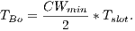
- Deafness Mitigation Mode: is triggered in the case that deafness prediction mechanism indicates that a neighbor node is suffering from deafness [ 25]. The behavior of this mode consists of sending a tone to the neighbor node that is suffering from deafness, as illustrated in Figure 3. In this case, the communication has a 3-way handshake (Tone-DATA-ACK). This mode performs receiver initiated communications. It is important to state that pulse/tone signals used in sender initiated communications and this tone used in receiver initiated communication signal are different, in such a way that by receiving a signal, a node can identify the kind of signal that is being received. This differentiation can be accomplished by varying these signals as regards to phase, frequency or amplitude, as described by [ 28]. This work assumes that these signals (pulse, tone, and receiver initiated communication tone) are transmitted in-band in different narrow portions of the band. For instance, it is considered that pulse is transmitted in high frequency portion of the band, tone is transmitted in low frequency portion of the band, while tone-ri (receiver initiated communication tone) is transmitted in mean portion of the band, as described in [ 16]. Here, the tone-ri signal is used to update DNAV properly, and to start a receiver initiated communication in order to mitigate deafness losses. The time transmission duration of the tone-ri is:
 , where
  denotes the synchronization time and the
  denotes the size of the DATA frame payload. This duration is necessary to the scheme of channel reservation based on pulse/tone signals proposed in [ 22] to work properly. This scheme allows DNAV to be properly updated also for the receiver initiated communications of DPTCR-DA. According to [ 16] [ 20],
  is enough for tone synchronization. Tones retransmissions do not occur when the node is operating on deafness mitigation mode.
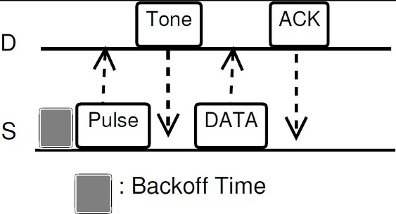
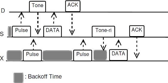
Figure 4: Different types of communications, for the topology of Figure 3: a) sender initiated; b) receiver initiated
An example of DPTCR-DA operation is available in Figure 4. Consider the topology displayed in Figure 3. Also, consider the existence of two data flows:  and
and  . It is also assumed that all packets are sent in directional mode and that some packets of each one of the flows were already successfully transmitted. In other words, node
  already “knows” the existence of both data flows. In the beginning, node
  waits its backoff time and try to start a sender initiated communication (standard mode) sending a pulse signal towards
  . Node
  verifies that it is the destination of the pulse signal and sends a tone back to
  . Then,
  and
and  exchange successfully DATA/ACK frames. In the meantime, node
  also tries to start a sender initiated communication (standard mode) to
  by sending a pulse signal. However, node
  is deaf for
  in this moment, since
  is beamforming towards
  . So, node
  cannot hear the pulse signals sent by node
  , thus causing the growing of exponential backoff window of node
  . This situation persists until the deafness prediction mechanism of node
  estimates that flow
  may be suffering from deafness. This mean that node
  estimated that node
  has packets to send to
  (identified as deafness by deafness prediction mechanism of node
  ). Therefore,
  enters in deafness mitigation mode, and sends a tone to node
  , trying to start a receiver initiated communication. When receiving the tone signal, node
  verifies that the destination of that signal is node
  , thus cancelling its backoff time and sending DATA frame to
  . So, the communication proceeds normally. Note that by using receiver initiated communications, DPTCR-DA may allow a better fairness in network resources assignment, as will be shown in Section 4.
4 Numerical and Empirical Results
This section analyzes the DPTCR-DA performance by comparing it with the DVCS [ 19] and RI-DMAC [ 10] protocols. The analytical analysis is presented below, followed by the simulation results.
The theoretical analysis aims to compare the maximum total throughput of the DPTCR-DA and DVCS enhanced with the IEEE 802.11 standard. The presented analytical results are based on the theoretical maximum throughput calculation for DPTCR-DA, comparing it against DVCS and RI-DMAC. Both sender and receiver initiated communications are addressed in the theoretical analysis.
4.1.1 Sender Initiated Communications
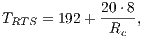
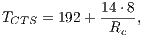
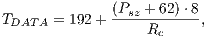
Both RI-DMAC and DVCS rely on RTS/CTS communication when sender initiated communications are employed. Hence, the theoretical results shown for DVCS applies to RI-DMAC and vice-versa. In which concerns to DVCS, the theoretical maximum throughput calculation can be obtained using the same methodology as described in [ 29]. Considering the notations defined in Table 2, the average transmission time ( ) is defined as follows:
 |
where:
 |
 |
 |
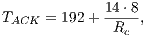 |
 |
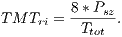
Using the equations aforementioned, the theoretical maximum throughput ( in Mbps) can be expressed as:
 | (5) |
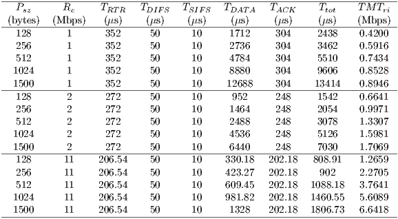
Table 5 shows the theoretical maximum throughput values for the DVCS and RI-DMAC computed with Equation 5. The table shows the TMT for channel transmission rates of  ,
,  and
and  Mbps, following the specifications of the IEEE 802.11b [ 1]. The packet size considered were
  ,
,  ,
,  ,
,  and
and  bytes. The TMT calculation for the DPTCR-DA, using the same set of channel transmission rate and packet size values were conduced. As the DPTCR-DA relies on pulse and tone signal instead of RTS/CTS, the
  is calculated as follows:
 | (6) |
where:
 |
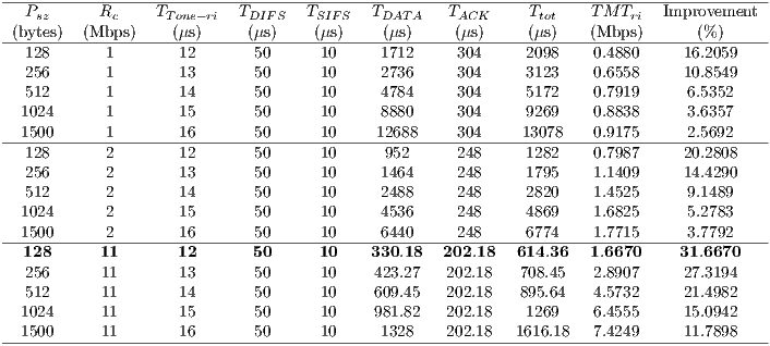
Using Equations 5 and 6 it is possible to calculate DPTCR-DA theoretical maximum throughput, which are displayed in Table 6. This table also shows the throughput improvement when employing the DPTCR-DA, as compared against the DVCS and RI-DMAC. As the  relation always holds, the DPTCR-DA allows for throughput improvements in all evaluated cases. The improvement gets higher when short packet size and higher transmission rate are considered. In such cases, the time spent exchanging control frames consumes a higher portion of
  . As displayed in Table 6, the referred improvement can be as high as
  (
( ,
,  ).
).


4.1.2 Receiver Initiated Communications
The theoretical analysis for the receiver initiated communications is similar to that presented above. However, in this analysis the DPTCR-DA is compared against the RI-DMAC only, as the DVCS does not support receiver initiated communications. Because DPTCR-DA receiver initiated communications inherits some characteristics of IEEE 802.11b, the presented analysis is also based on [ 29]. In this case, note that backoff time is not included in  calculation, since the receipt of an RTR frame cancels the remaining backoff time. The receiver initiated TMT (
 ), when considering the notations presented in Table 2, can be defined as:
 | (7) |
where:
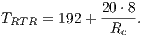 |
The  and
and  follows from previous definitions and the theoretical maximum throughput for receiver initiated communications (
 in Mbps) was calculated by using the following equation:
 | (8) |
The results of this calculation are displayed at Table 7. In this calculation, the considered values of packet size and channel transmission rate were the same used for sender initiated communications. An analogous calculation was performed to compute the TMT of DPTCR-DA. Note that backoff time is not included in  calculation again, once the receipt of a tone-ri cancels the remaining backoff time. Therefore, the average total transmission time (
 ) is now defined as follows:
 | (9) |
where
 |
These equations allow the calculation of  for DPTCR-DA. The results of this calculation are shown in Table 8. The packet size and channel transmission rate were the same as those in the sender initiated case. Table 8 also shows the throughput improvement that DPTCR-DA provides when compared against RI-DMAC. As before, the relation
 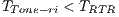 always holds. Similar to sender initiated communications, DPTCR-DA improvement raises when packet size is short and channel transmission rate is high. As already explained, this occurs because in these cases the time spent with RTR represents a higher portion of
  . The throughput improvement provided by DPTCR-DA for receiver initiated communications can be as high as
  , which shows that the DPTCR-DA provides significant gains as compared to the RI-DMAC. The simulation results will be presented in the next subsection.
This section presents an empirical analysis of the DPTCR-DA, DVCS and RI-DMAC. The empirical results are compared with the theoretical ones to validate the referred analysis. As it will be shown, the use of pulse/tone signals instead of frames for both sender and receiver initiated communications provides significant improvement for all evaluated cases. For this evaluation, the EXata simulator, version 2.0, was used [ 18]. The EXata simulator has a number of features, such as realistic antenna models and patterns, propagation models (free space, two-ray), the IEEE 802.11b standard and a number of other protocols in the TCP/IP stack. The EXata simulator also addresses the features contained in Qualnet and GloMoSim [ 18]. It is important to recall that these simulators are widely used in related studies.
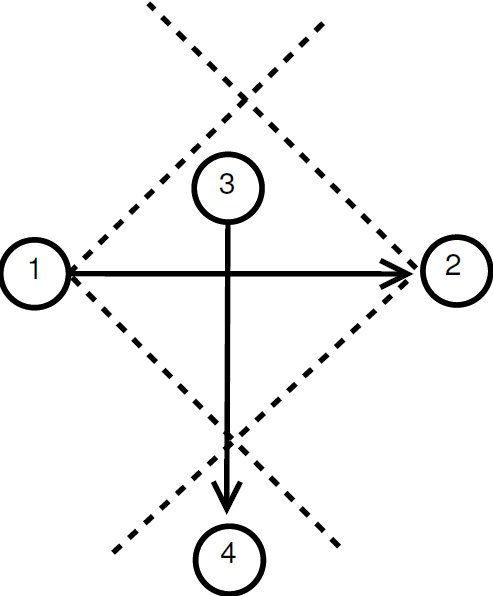
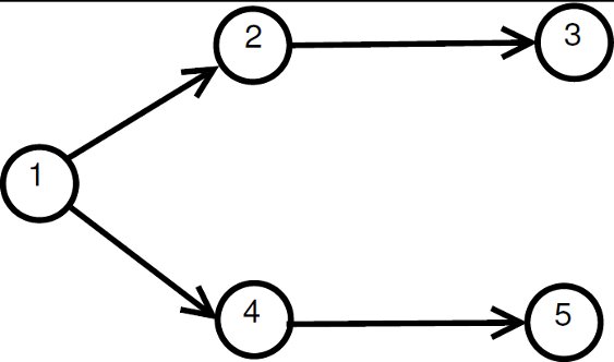
The EXata incorporates the DVCS and the RI-DMAC has been implemented. The scenarios considered for the empirical analysis are depicted in Figure 5. The figure shows three different scenarios: ( ) the first scenario, depicted in Figure 4, aims to validate the
  values obtained in the simulation with the analytical results; (
 ) the second scenario (Figure 4) aims to show that DNAV setting are properly updated when DPTCR-DA is used – node
  shall receive the control messages exchanged by nodes
  and
and  ; and (
 ) the third scenario (Figure 4) illustrates a case where nodes
  and
and  may be deaf towards the direction of node
  . This last scenario aims to show that DPTCR-DA can mitigate deafness. Every arrow in Figure 5 represents a CBR flow. Although DPTCR-DA is able to operate with other antenna types, in the simulations it was assumed the use of a switched beam antenna with 8 sectors of
  . Packet size and channel transmission rate values has the same values used in the theoretical analysis. The other relevant EXata parameters are shown at Table 3. Also, it was assumed that
  and
and  dB, once these values are reasonable for the antenna considered in this work [ 12] [ 26] [ 27]. Each one of the presented results is the average of 20 simulations. The presented results evaluate DVCS, RI-DMAC and DPTCR-DA in terms of fairness, end-to-end delay, jitter and throughput, which are widely used metrics [ 9]. In the presented analysis, mobility was not addressed as is commonly accepted for MAC layer protocol evaluations [ 10] [ 19].

As illustrated in Figure 4.2, this scenario has two nodes and a CBR flow ( ). For this flow, the considered packet arrival interval (
 ) was defined as
  ms. The packet size and the transmission data rate values considered were the same used in theoretical analysis. In the first scenario, DPTCR-DA was compared against DVCS as deafness does not occur in this setting. Thus, in this case RI-DMAC (and DVCS-DA) will have the same behavior of DVCS, since the sender initiated communications of RI-DMAC and DVCS-DA are based on DVCS scheme. Results for the first scenario are displayed in Table 9 for channel transmission rate (
 ) of
) of  ,
,  and
and  Mbps. As can be seen, the simulated values for DPTCR-DA are similar to those obtained in the theoretical calculation (Tables 5 and 6). As shown in Table 9, in all considered cases, DPTCR-DA attained higher throughput than DVCS scheme. In the best case, the obtained throughput improvement was over
  higher than that experienced by the DVCS. As in the theoretical analysis, the DPTCR-DA attains better results when
  is high and
  is low. Note that the above results are consistent with the theoretical analysis.

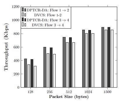
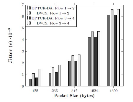
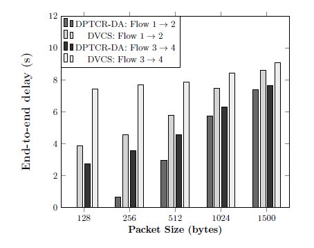
The second scenario consists of four nodes and two CBR flows:  and
and  as shown in Figure 4. Again, the DPTCR-DA is compared against DVCS as both RI-DMAC and DVCS have similar characteristics when deafness does not occur. The simulation results for this scenario are displayed in Figures 6, 7, 8. These figures show the DPTCR-DA and DVCS comparison in terms of throughput, jitter and end-to-end delay, respectively. In all addressed cases, DPTCR-DA was able to attain a superior performance than DVCS. Indeed, when using DPTCR-DA, it was able to provide throughput improvement up to
  and
and  for flows
  and
and  , respectively. The jitter reduces
  and
and  for flows
  and
and  , respectively. Compared to the DVCS, the end-to-end delay obtained by the DPTCR-DA diminishes
  and
and  for flows
  and
and  , respectively.
The above results shows that the DPTCR-DA allows neighboring nodes to correctly set their DNAV counter, once flows  and
and  are being served simultaneously. The correct DNAV update indicates also that the mechanism which predicts the signal source and duration works properly, as expected for the considered precisions of angle of arrival (
 ) and received signal strength (
 dB).
dB).
 Mbps
Mbps
 Mbps
Mbps
 Mbps
Mbps The third scenario consists of five nodes and four CBR flows as depicted in Figure 4. For all the considered flows, the packet arrival interval ( ) in this scenario were
  ,
,  and
and  ms. The packet size was considered to be equal to
  bytes, and date transmission rate was considered to be equal to
  Mbps. Note that this scenario may cause nodes
  and
and  to be deaf to the incoming packets from node
  . Thus, the goal of this scenario is to show that DPTCR-DA is able to mitigate deafness problem in cases where there are alternate flows. The results in terms of throughput for each flow are displayed in Table 10. This table also displays the fairness index values. It is important to state that the fairness index is defined in this work as the Jain index [ 30] (Equation 10). The Jain index provides values in the interval [0,1], since it is a normalized index. Therefore, a higher value of fairness index means a fair assignment of network resources [ 30]. Let,
  denote the throughput of the flow
  . So, the fairness index can be defined as follows [ 30]:
 | (10) |
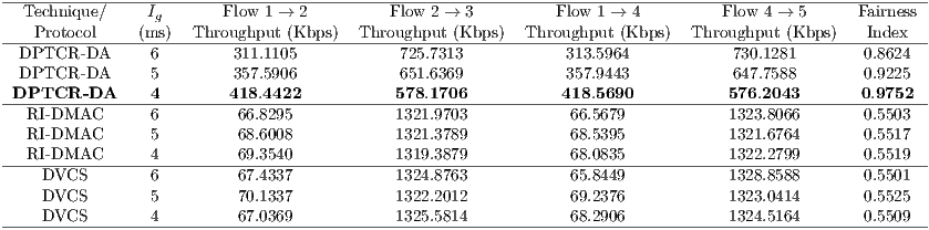
As expected, the simulation results show that RI-DMAC protocol behaves just like DVCS in this case. This occurs since RI-DMAC deafness prediction is based on next packet information. However, in this case node  has more than one flow, which causes the occurrence of alternate packets in the queue of node
  . As can be inferred from Table 10, RI-DMAC and DVCS have an unfair assignment of network resources. Nodes
  and
and  are deaf to node
  , thus leading to a low throughput of flows
  and
and  . On the other hand, the DPTCR-DA is able to mitigate deafness in this case because DPTCR-DA uses network resources in a fairer way. This can be inferred from Table 10 where a more equal division among throughput flows can be observed. Note that the throughput of flows
  and
and  is more than
  times higher (
 higher) than when using DVCS or RI-DMAC. In which concerns to fairness index, in all cases, the DPTCR-DA presented better results than RI-DMAC and DVCS. DPTCR-DA is able to provide a fairness index nearly
  higher than RI-DMAC or DVCS, which indicates a remarkable improvement on the fairness of network resources assignment.
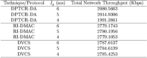
Although DPTCR-DA provides a better fairness than RI-DMAC, it has a lower network throughput than RI-DMAC, as shown in Table 11. Such reduction is mainly due to the time spent to mitigate deafness. Clearly, fairness and throughput are contrasting parameters. One can easily improve throughput at the expense of fairness. As deafness cannot be handled by RI-DMAC in this case, the overall network throughput is higher (at the expense of flows  and
and  ). It is important to state that, in a multihop scenario, it is paramount to improve packet relay time. This is accomplished by DPTCR-DA, while RI-DMAC and DVCS would not be able to cope with that.
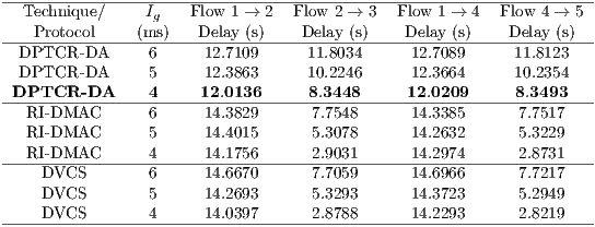
The empirical evaluation was also held in terms of jitter and end-to-end delay. The results for these metrics are displayed in Tables 12 and 13. In terms of jitter, DPTCR-DA is able to provide a decrease of  for flows
  and
and  when compared to RI-DMAC or DVCS. Following the same trend of throughput results, flows
  e
e  have a lower performance when DPTCR-DA is used. As regards to end-to-end delay, the use of DPTCR-DA causes a loss of performance for flows
  and
and  . As stressed in Table 13, the flows that are impaired by deafness problem (
 and
and  ) presented an end-to-end delay by
  lower using DPTCR-DA.
This section presented a detailed evaluation of the DPTCR-DA, showing its strengths in a number of scenarios and conditions. As compared to the DVCS and RI-DMAC, the DPTCR-DA was able to improve throughput, reduce jitter and end-to-end delay in all sender initiated scenarios. In deafness prone scenarios, the results have shown that the DPTCR-DA was able to mitigate deafness and provide significant gains in terms of fairness, jitter, end-to-end delay and throughput of the affected flows. Clearly, DPTCR-DA is able to provide significant improvements by efficiently exploring the directional communication characteristics.

The use of directional antennas has been considered a promising alternative to improve spatial division and throughput. However, to realize its benefits, efficient directional MAC protocols are needed. This work shows the benefits as well the problems associated with directional communications. Among the problems discussed, the deafness is one which has received considerable attention in the literature.
In this context, this paper first presents a deafness mitigation technique, termed DPTCR-DA. The DPTCR-DA is based on traffic flow information to estimate deafness occurrence. DPTCR-DA also incorporates a prominent and innovative way to perform channel reservation using pulse/tone signals instead of frames for both sender and receiver initiated communications. Thus, the DPTCR-DA constitutes a powerful deafness mitigation technique while providing remarkable improvements in terms of throughput, fairness, jitter, and end-to-end delay of the flows that are affected by the deafness problem. The DPTCR-DA also attained better performance results for all sender initiated communications in the evaluated scenarios. As future works, it would be interesting to evaluate different election policies, in which concerns to the node that receives a tone in the beginning of a receiver initiated communication. The main motivation for this evaluation is the existence of discussions about which policy is the most efficient, as described in [ 31]. Evaluation of the energy consumption gains shall be conduced as well.
This work was partially supported by CNPq.
<[1] a id="Xieee2007"> IEEE, “IEEE Standard for information technology-telecommunications and information exchange between systems-local and metropolitan area networks - specific requirements - part 11: Wireless lan medium access control (mac) and physical layer (phy) specifications,” Institute of Electrical and Electronics Engineers, IEEE Standard 802.11, December 2007.
[2] J. Bordim, A. Barbosa, M. Caetano, and P. Barreto, “IEEE802. 11b/g standard: Theoretical maximum throughput,” in Networking and Computing (ICNC), 2010 First International Conference on. IEEE, 2010, pp. 197–201.
[3] P. Gupta and P. Kumar, “The capacity of wireless networks,” IEEE Transactions on Information Theory, vol. 46, no. 2, pp. 388–404, 2000.
[4] S. Kumar, V. Raghavan, and J. Deng, “Medium Access Control protocols for ad hoc wireless networks: A survey,” Ad Hoc Networks, vol. 4, no. 3, pp. 326–358, 2006.
[5] R. Ramanathan, “Antenna Beamforming and Power Control for Ad Hoc Networks,” in Mobile ad hoc networking. Wiley-IEEE Press, 2004, vol. 1, ch. 5, pp. 139–173.
[6] P. Mohapatra and S. Krishnamurthy, AD HOC NETWORKS: technologies and protocols. Springer, 2005.
[7] P. Azevêdo, M. Caetano, and J. Bordim, “A packet aggregation mechanism for real time applications over wireless networks,” International Journal of Networking and Computing, vol. 2, no. 1, pp. 18–40, 2012.
[8] P. Krishnamurthy and S. Krishnamurthy, “Use of smart antennas in ad hoc networks,” in AD HOC NETWORKS: technologies and protocols. Springer, 2005, vol. 1, ch. 7, pp. 197–226.
[9] R. Choudhury, X. Yang, R. Ramanathan, and N. Vaidya, “Using directional antennas for medium access control in ad hoc networks,” in Proceedings of the 8th annual international conference on Mobile computing and networking. ACM, 2002, pp. 59–70.
[10] M. Takata, M. Bandai, and T. Watanabe, “RI-DMAC: a receiver-initiated directional MAC protocol for deafness problem,” International Journal of Sensor Networks, vol. 5, no. 2, pp. 79–89, 2009.
[11] J. Bordim and K. Nakano, “Deafness resilient mac protocol for directional communications,” IEICE TRANSACTIONS on Information and Systems, vol. 93, no. 12, pp. 3243–3250, 2010.
[12] A. Amiri Sani, L. Zhong, and A. Sabharwal, “Directional antenna diversity for mobile devices: characterizations and solutions,” in Proceedings of the sixteenth annual international conference on Mobile computing and networking. ACM, 2010, pp. 221–232.
[13] A. Subramanian and S. Das, “Addressing deafness and hidden terminal problem in directional antenna based wireless multi-hop networks,” Wireless Networks, vol. 16, no. 6, pp. 1557–1567, 2010.
[14] R. Choudhury and N. Vaidya, “Deafness: A MAC problem in ad hoc networks when using directional antennas,” in Network Protocols, 2004. ICNP 2004. Proceedings of the 12th IEEE International Conference on. IEEE, 2005, pp. 283–292.
[15] G. Li, L. Yang, W. Conner, and B. Sadeghi, “Opportunities and challenges for mesh networks using directional antennas,” in Proceedings of First IEEE Workshop Wireless Mesh Networks (WiMesh’05). IEEE, 2005, pp. 106–116.
[16] K. Shih, W. Liao, H. Chen, and C. Chou, “On avoiding RTS collisions for IEEE 802.11-based wireless ad hoc networks,” Computer Communications, vol. 32, no. 1, pp. 69–77, 2009.
[17] Z. Haas and J. Deng, “Dual busy tone multiple access (dbtma)-a multiple access control scheme for ad hoc networks,” IEEE Transactions on Communications, vol. 50, no. 6, pp. 975 –985, jun 2002.
[18] Scalable Network Technologies, “Simulador EXata,” URL: http://www.scalable-networks.com/exata/, 2011.
[19] M. Takai, J. Martin, R. Bagrodia, and A. Ren, “Directional virtual carrier sensing for directional antennas in mobile ad hoc networks,” in Proceedings of the 3rd ACM international symposium on Mobile ad hoc networking & computing. ACM, 2002, pp. 183–193.
[20] J. Ma, H. Sekiya, A. Nagasaki, N. Komuro, and S. Sakata, “MAC Protocol for Ad Hoc Networks Using Smart Antennas for Mitigating Hidden and Deafness Problems,” IEICE TRANSACTIONS on Communications, vol. E95-B, no. 11, pp. 3545–3555, 2012.
[21] S. Basagni, M. Conti, S. Giordano, and I. Stojmenović, Mobile ad hoc networking. Wiley-IEEE Press, 2004.
[22] L. Guimarães and J. Bordim, “Utilização de pulse/tone como mecanismo de reserva de canal em comunicações direcionais,” in XXXVIII Conferencia Latinoamericana en Informática. Centro Latinoamericano de Estudios en Informática, 2012, pp. 515–523.
[23] M. Gast, 802.11 wireless networks: the definitive guide. O’Reilly Media, 2002.
[24] M. Takata, M. Bandai, and T. Watanabe, “A receiver-initiated directional MAC protocol for handling deafness in ad hoc networks,” in IEEE International Conference on Communications (ICC’06), vol. 9. IEEE, 2006, pp. 4089–4095.
[25] P. Dias, L. Guimarães, L. Nunes, M. Caetano, and J. Bordim, “Proposta de tratamento do problema de surdez de antenas em comunicações direcionais,” in XXX Simpósio Brasileiro de Telecomunicações. Sociedade Brasileira de Telecomunicações, 2012, pp. 540–544.
[26] G. Giorgetti, S. Maddio, A. Cidronali, S. Gupta, and G. Manes, “Switched beam antenna design principles for angle of arrival estimation,” in Wireless Technology Conference, 2009. EuWIT 2009. European. IEEE, 2009, pp. 5–8.
[27] J. Lee, D. Kim, C. K. Toh, T. Kwon, and Y. Choi, “A Table-driven AOA Estimation Algorithm for Switched-beam Antennas in Wireless Networks,” in 11th European Wireless Conference 2005-Next Generation Wireless and Mobile Communications and Services (European Wireless). VDE, 2005, pp. 1–6.
[28] A. Tanenbaum, Computer Networks, 4th ed. Prentice Hall Professional Technical Reference, 2002.
[29] J. Jun, P. Peddabachagari, and M. Sichitiu, “Theoretical maximum throughput of IEEE 802.11 and its applications,” in Second IEEE International Symposium on Network Computing and Applications, 2003. (NCA 2003). IEEE, 2003, pp. 249–256.
[30] R. Jain, D. Chiu, and W. Hawe, A quantitative measure of fairness and discrimination for resource allocation in shared computer system. Eastern Research Laboratory, Digital Equipment Corporation, 1984.
[31] T. Bonfim and M. Carvalho, “Reversing the IEEE 802.11 backoff algorithm for receiver-initiated MAC protocols,” in Wireless Communications and Mobile Computing Conference (IWCMC), 2012 8th International. IEEE, 2012, pp. 269–274.

