


Servicios Personalizados
Revista

Articulo
 Inglés (pdf)
 Articulo en XML
 Referencias del artículo
Links relacionados
Compartir

 Permalink
CLEI Electronic Journal
versión On-line ISSN 0717-5000
CLEIej vol.15 no.2 Montevideo ago. 2012
Abstract
Code size is a primary concern in the embedded computing community. Minimizing physical memory requirements reduces total system cost and improves performance and power efficiency. VLIW processors rely on the compiler to statically encode the ILP in the program before its execution, and because of this, code size is larger relative to other processors. In this paper we describe the co-design of compiler optimizations and processor architecture features that have progressively reduced code size across three generations of a VLIW processor.
Spanish abstract:
El tamaño del código es la principal preocupación en la comunidad de computación empotrados. Reducir al mínimo los requisitos de memoria física reduce el coste total del sistema y mejora la rendimiento y eficiencia energética. Los procesadores VLIW confían en que el compilador estáticamente codifica la ILP en el programa antes de su ejecución, y debido a esto, el tamaño del código es más grande en relación a otros procesadores. En este trabajo se describe el co-diseño de las optimizaciones del compilador y la arquitectura del procesador, características que han de reducir progresivamente el tamaño del código a través de tres generaciones de un procesador VLIW.
Keywords: Instruction level parallelism, code compression, VLIW, ILP
Spanish keywords: paralelismo a nivel de instrucciones, compresión de código, VLIW, ILP
Received 2011-12-15, Revised 2012-05-16, Accepted 2012-05-16
VLIW processors are well-suited for high performance embedded applications, which are characterized by mathematically oriented loop kernels and abundant ILP. In contrast to superscalar processors, which have dedicated hardware to dynamically find ILP at run-time, VLIW architectures rely completely on the compiler to find ILP before program execution. The compiler can, in many cases, exploit ILP better than hardware, and the saved silicon space can be used to reduce cost, save power, or add more functional units (1). Therefore, it is critical that a VLIW processor be a good compiler target.
Because ILP must be explicitly expressed in the program code, VLIW compiler optimizations often replicate instructions, increasing code size. While code size is a secondary concern in the computing community overall, it can be significant in the embedded community. Minimizing the amount of physical memory reduces total system cost. Reducing code size improves system performance by allowing space for more code in on-chip memory and program caches. Code size reduction improves power efficiency, because it reduces the energy required to fetch instructions from memory (2, 1, 3)
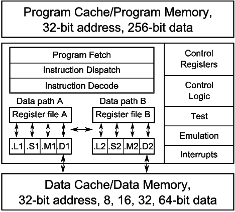
Figure 1 is a block diagram of the C6X processor. The first generation C6X (C6X-1) processors are the TMS320C62 (C62) and TMS320C67 (C67). The C6X-1 is a fully pipelined VLIW processor, which allows eight new instructions to be issued per cycle. All instructions can be optionally guarded by a static predicate. If an instruction’s predicate operand evaluates to false, then the results of the instruction are anulled. The C62 provides a foundation of integer instructions. It has 32 static general-purpose registers, partitioned into two register files. A small subset of the registers may be used as predicates. Load instructions have four delay slots, multiplies have one delay slot, and branches have five delay slots. Other instructions have no delay slots. The C67 adds floating point instructions.
The second generation C6X (C6X-2) processor is the TMS320C64 (C64), which builds on the C62 by removing scheduling restrictions on existing instructions and providing additional instructions for SIMD packed-data processing. The C6X-2 processors increase the size of register file by providing an additional 32 static general-purpose registers.
The third and latest generation C6X (C6X-3) processors are the TMS320C64 (C64+) and the TMS320C674 (C674). The C6X-3 doubled the number of multipliers and added new architecture features to improve code size and software-pipelined loop performance. The C674 includes the C67 floating point instructions.
The C6X processors are supported by an optimizing compiler (4). The structure and operations of a compiler are well documented (5, 6, 7, 8). The compiler implements important optimization phases such as function inlining, loop nest optimization, data dependence analysis, software pipelining, and many more. The compiler is absolutely critical for exploiting ILP.
1.2 Encoding Wide Instructions
Each instruction on the C6X-1 processors is 32-bit. Instructions are fetched eight at a time from program memory in bundles called fetch packets. Fetch packets are aligned on 256-bit (8-word) boundaries. The C6X-1 processors can execute from one to eight instructions in parallel. Parallel instructions are bundled together into an execute packet. As fetch packets are read from program memory, the instruction dispatch logic extracts execute packets from the fetch packets. All of the instructions in an execute packet execute in parallel. Each instruction in an execute packet must use a different functional unit.
The execute packet boundary is determined by a bit in each instruction called the parallel-bit (or p-bit). The p-bit (bit 0) controls whether the next instruction executes in parallel. The p-bits are scanned from lower to higher addresses. If the p-bit of instruction  is
is  , then instruction
  is part of the same execute packet as instruction
  . If the p-bit of instruction
  is
is  , then instruction
  is part of the next execute packet.
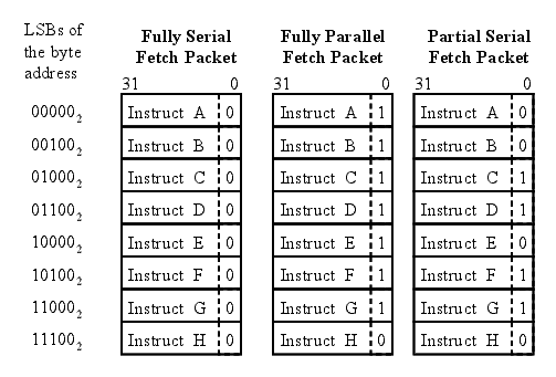
Figure 2 shows three p-bit patterns for fetch packets, which result in the following execution sequences for the eight instructions: fully serial, fully parallel, and partially serial. The least significant bits (LSBs) of the program memory address shows how the fetch packets are laid out in memory. Each instruction with a p-bit set to  marks the end of an execute packet. The fully serial fetch packet has eight execute packets each made up of one instruction. The fully parallel fetch packet has one execute packet made up of eight instructions, which will execute in parallel. The partially serial fetch packet has four execute packets.
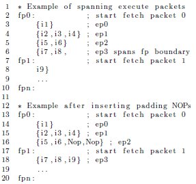
On the C6X-1 processors, execute packets cannot span a fetch packet boundary. Therefore, the last p-bit in a fetch packet is always set to  , and each fetch packet starts a new execute packet. Execute packet are padded with explicit parallel NOP instructions to prevent subsequent execute packets from spanning a fetch packet boundary. On the C6X processor, NOP instructions may execute on any of the eight functional units. Figure 3 shows how parallel NOP instructions are used to align spanning execute packets. Instructions in { } are part of the same execute packet and, therefore, will execute in parallel.
Except for a few special case instructions such as the NOP, each instruction has a predicate encoded in the first four bits. Figure 4 is a generalization of the C6X 32-bit three operand instruction encoding format. The predicate register is encoded in the condition (creg) field, and the z-bit encodes the true or not-true sense of the predicate. The dst, src2, and src1 fields encode operands. The x-bit encodes whether src2 is read from the opposite cluster’s register file. The op field encodes the operation and functional unit, and the s-bit specifies the cluster that the instruction executes on.

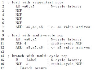
NOP instructions occur frequently in VLIW programs and as a result increase code size. Often NOP instructions are executed for multiple sequential cycles. The C6X processors include a multi-cycle NOP for encoding a sequence of NOP instructions. Figure 5 shows how four sequential NOP instructions are encoded as one multi-cycle NOP 4.
While the fetch-execute packet encoding scheme and multi-cycle NOP instruction improved the code size of the C6X-1 processors relative to previous VLIWs, embedded applications required further code size reductions. To this end, it was proposed that the C6X-2 processors allow execute packets to span fetch packet boundaries with some minimal restrictions, thus reducing code size by eliminating the need for padding NOP instructions. Further, we proposed new instructions, similar to the multi-cycle NOP, that remove pipeline NOP instructions (9, 10, 11).
Because VLIW processors have exposed pipelines, NOP instructions are inserted to compensate for instruction latencies. A latency is the number of cycles it takes for the effect of an instruction to complete. Instruction scheduling is used to fill the latency or delay slots with other useful instructions. Assuming that other instructions are unavailable for execution during the instruction latency, explicit pipeline NOPs are inserted after the instruction issues to maintain correct program execution. On the C6X processor, the load (LD) and branch (B) instructions have five and six cycle latencies, respectively. In Figure 5, the delay slots of load and branch instructions are filled with NOP instructions.
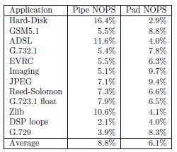
The breakdown of pipeline and padding NOP instructions occurring in a set of embedded applications is shown in Figure 6. These data show that 8.8% and 6.1% of all instructions are pipeline and padding NOPs, respectively. The control-oriented applications had more pipeline NOP instructions, and the loop-oriented applications had more padding NOP instructions. Loop-oriented code with high degrees of ILP contains more padding NOP instructions, because execute packets tend to be larger in loop code, thus increasing the likelihood of spanning execute packets. The opposite occurs in control-oriented code with lower degrees of ILP, because execute packets are smaller and, therefore, pack more efficiently into fetch packets. Because it has less ILP and is characterized by short test-and-branch sequences, pipeline NOPs occur more often in control-oriented code.
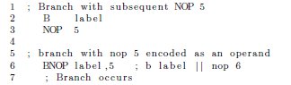
We proposed a new instruction format that implements a variable delay operation (10, 12), that in effect encodes subsequent NOP instructions as an operand. For example, because of their long latency, branch instructions are often followed by a multi-cycle NOP instruction. The Branch with NOP (BNOP) instruction encodes the subsequent NOP instructions as an operand (see Figure 7). The effect is that the NOP is issued in parallel with the instruction requiring the latency. The NOP operand ranges from zero to the maximum latency of the instruction.
We found that this new instruction format reduce average code size by 6%. Control-oriented code, which contains more branches, saw a larger improvement. Loop-oriented code benefited more from eliminating the restrictions on spanning execute packets.
3 Software-pipelined Loop Collapsing
Software pipelining is a powerful loop-based transformation that exploits the ILP across the iterations of a loop. Modulo scheduling, an algorithm for implementing software pipelining, takes the N instructions in a loop and forms an M-stage pipeline as if a vector functional unit were being specifically designed to execute the loop body.
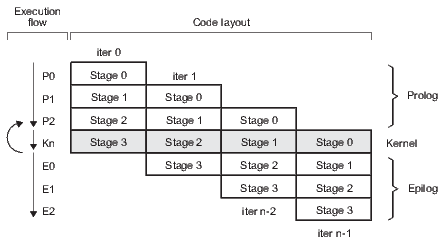
Modulo scheduling is motivated by the development of pipelined hardware functional units. The initiation interval (II) is the rate at which new loop iterations are started (13, 14). The total schedule length (TL) is the number of cycles to complete one loop iteration. The schedule for a single iteration is divided into a sequence of stages, each with a length of II. The number of stages is SC =  . In the steady state of the execution of the software-pipelined loop, each of the stages will execute in parallel. The instruction schedule for a software-pipelined loop has three components: a prolog, a kernel, and an epilog, as shown in Figure 8. The kernel is the instruction schedule that will execute the steady state. In the kernel, an instruction scheduled at cycle
  will execute in parallel with all instructions scheduled at cycle
  . This is known as the modulo constraint and is the source of the term modulo scheduling.
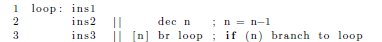
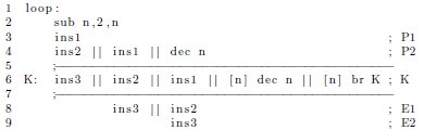
While software pipelining positively affects performance, it negatively impacts code size. As an example, assume a simple loop that consists of three generalized instructions (ins1, ins2, and ins3), a decrement, and a conditional branch back to the beginning. Suppose ins2 depends on the result of ins1, and ins3 on the result of ins2. In the absence of software pipelining, a possible schedule for this code on a VLIW processor is shown in Figure 9.
The || operator denotes instructions that execute in parallel. The operand [n] is a predicate that guards the branch. When the value of the register n is non-zero, the branch is taken. When n is zero, the instruction is nullified. For simplicity, all instructions are assumed to be single-cycle with no delay slots.
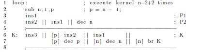
In the above schedule, very little parallelism has been exploited because ins1, ins2, and ins3 must execute in order within the given loop iteration. Thus, each loop iteration takes three cycles to complete. Software pipelining improves performance by overlapping multiple consecutive iterations of the loop. For example, a pipelined version of the loop is shown in Figure 10. Although the first iteration requires  cycles to complete, all successive iterations complete at a rate of
  iteration per cycle. Thus, software pipelining has transformed the three-cycle loop into a one-cycle loop.
The two most common causes of code growth associated with software pipelining are the basic replication of loop iterations and compensation code.
- Instruction replication: As can be seen in Figure 10, the final code size is roughly
 times the original code size. The kernel is roughly the size of the original loop. The prolog and epilog combined are roughly
  .
. - Compensation code: For a loop to be eligible for software pipelining, the loop must execute at least SC iterations. Recall that SC is the number of iterations that are concurrently executing during the kernel. For example, in Figure 10 the loop will always execute three or more iterations. Therefore, the pipelined version is only safe when the original trip count is at least three. When the compiler is unable to determine that the trip count is large enough, it must either suppress software pipelining or generate compensation code: two versions of the loop (pipelined and non-pipelined) and a run-time check to choose between them. However, this clearly increases code size.
Software-pipelined loop collapsing is a compile-time technique that folds the prolog and epilog stages into the kernel. In the software-pipelined loop in Figure 10, observe that the only difference between the kernel and the first stage of the epilog (ignoring loop control instructions) is that ins1 is executed in the kernel but not in the epilog. Suppose it were safe to speculatively execute (meaning that it would not cause incorrect program results) ins1 one extra time. Then the kernel could execute one extra time and skip the first stage of the epilog as shown in Figure 11.

The first epilog stage is now collapsed back into the kernel, replacing an epilog stage with an extra iteration of the kernel. Consequently, before the loop the trip counter is incremented by one, so that the pipelined loop executes the same number of iterations (produces the same number of results) as the original loop.
Once an epilog stage has been collapsed, the minimum number of iterations that will be completely executed (shortest path through loop) is reduced by one, from three to two. Although a third iteration is started, only ins1 from this iteration is executed. There is no harm in executing this instruction an extra time. Thus, this loop can be safely executed whenever the original trip count is at least two (as opposed to three).
The same process is now applied to epilog stage 2 as shown in Figure 12. In this case however, ignoring loop control instructions, there are two instructions that do not execute during epilog stage 2: ins1 and ins2. Assume the compiler determined that ins1 could be safely speculatively executed a second time, but ins2 could not. Therefore, to collapse stage 2, a predicate is placed on ins2 to guard against over-execution. Observe that, before loop execution begins, the new predicate register is initialized to one less than the trip counter, so that ins2 is not executed during the last iteration of the kernel.
In this example, the cost of eliminating the second epilog stage (the addition of two instructions) outweighs the benefit (eliminating one instruction). In practice, however, epilog stages are usually much larger. The pipelined version of the loop, with the fully collapsed epilog, is now safe for all trip counts greater than zero. The shortest path through the code now computes only one full iteration of the loop. Therefore, if the compiler did not have any information about the trip counter, it would have been worth collapsing the last epilog stage to eliminate the need for compensation code. Prologs are collapsed in the same way, except that it must be safe to over-execute an instruction before the loop rather than afterwards.
Using 72 loop kernels, we showed that collapsing decreased loop code size by over 30% (15). Greater benefit was derived from epilog collapsing than from prolog collapsing. In most cases, epilogs can be completely collapsed using at most one predicate register. Prologs frequently cannot be completely collapsed and often require a predicate register per collapsed stage.
In general, collapsing  stages across a combination of epilog or prolog collapsing obviates the need for compensation code. Thus, collapsing becomes a very important optimization when loop trip counts are not available at compile-time.
A hardware loop buffer is a program cache specialized to hold a loop body. The motivation for building hardware loop buffers is to reduce power consumption and in some cases improve performance (16). Typically, a loop buffer is small, compared to a full blown program cache, and placed close to a processor’s execution units. Therefore, instructions executed from the loop buffer require less power, since the processor is not required to enable the memory system and fetch logic. In addition, the instructions may be stored in a decoded format bypassing the processor’s decode logic. A zero overhead loop buffer has an additional function to eliminate the need for an explicit branch instruction in the program source code. The loop buffer performs the branch automatically. The loop body is demarcated by special instructions.
We proposed a loop buffer specialized to improve the performance of software-pipelined loops specifically in the following areas (17)
- Code size: Replicated instructions in the software-pipelined loop prolog and epilog instruction schedule significantly increase code size.
- Compensation code: If the bounds of the loop trip counter are unknown, the compiler must generate additional compensation code, which increases code size and often decreases performance.
- Fetch/decode power: Fetching from program memory and decoding the replicated instructions in the software-pipelined loop prolog and epilog requires additional power.
- Instruction speculation: The compiler speculates instructions as part of the process of collapsing software-pipelined loops. Because the results of these instructions are never used and many are memory operations, they waste power and have side-effects in the memory system that can degrade performance.
- Interrupt latency: The latency increases when interrupts are disabled around software-pipelined loops.
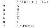
A modulo loop buffer (MLB) (18) is a hardware loop buffer that is specialized to exploit the regular pattern that occurs in software-pipelined loops. On the C6X-3 processor, the SPLOOP instruction marks the beginning of a loop body that is to execute from the MLB. The operands of the SPLOOP instruction encode the II. The SPKERNEL instruction marks the end of the loop body instructions. In Figure 13 A, B, C, D, and E are the instructions of a single loop iteration with an II of 1. SPLOOP and SPKERNEL demarcate the loop body.
The MLB records and executes future loop iterations and eliminates replicated instructions from the software-pipelined loop prolog and epilog. Figure 14 shows how the loop body is executed. A:n through E:n are the stages of the nth iteration in the software-pipelined loop. The Instr Fetch column shows the loop body instructions fetched from program memory and stored in the MLB. After SPKERNEL is encountered, instruction fetch from program memory is disabled; instructions are fetched only from the MLB until the loop completes. The Loop Buffer Fetch column shows the fetch of instructions from the MLB, and the Execute column shows the instructions that are actually executed.
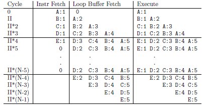
The loop body is a single iteration, modulo scheduled software-pipelined loop. TL (total schedule length) is the length of the loop body in cycles starting with the cycle after the SPLOOP instruction and ending with the cycle at the SPKERNEL instruction. It consists of  stages of II cycles each. The execution of the prolog, kernel, and epilog are generated from copies of this single iteration time shifted by multiples of II cycles and overlapped for simultaneous execution (see Figure 14).
As the instructions in the loop body are fetched and executed, they are stored in the loop buffer along with their insertion order. By the time the entire loop body has been inserted into the loop buffer, the loop kernel is present and can execute entirely from there. When the software-pipelined loop enters the epilog the loop buffer disables the execution of instructions in the order that they were inserted.
Clearly, the MLB reduces code size and improves power efficiency by eliminating the overlapped copies of the instructions in the loop body. Unlike software-pipelined loop collapsing, the MLB reduces code size without requiring instruction speculation. This improves power efficiency by eliminating the fetch, decode, and execution of unused speculated instructions. The MLB on the C6X-3 processors implements other capabilities such as the ability to overlap pre- and post-loop instructions with the execution of the prolog and epilog, support for nested loops, and an early-exit feature that eliminates compensation code. In addition, the MLB improves interrupt latency.
There are two limits in the implementation of the loop buffer: the total size of the loop buffer and the maximum loop body length. The size is the number of execute packets in the kernel; therefore, this limits the maximum II for a software-pipelined loop in the MLB. The maximum loop body length in cycles (maximum TL) sets the sizes of internal bookkeeping information built during the prolog and used during the epilog to pipe down the loop.
Figure 15 illustrates the potential benefits of the MLB using several performance parameters on a small set of DSP and multi-media applications including gsmefr, g.723.1, g.729, JPEG, 95 loop kernels, and Reed-Solomon. These results are an upper bound since they assume that all software-pipelined loops can fit in the loop buffer.
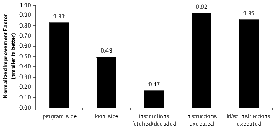
The program size parameter measures relative code-size reduction in the entire program, and the loop size parameter measures relative code-size reduction in the software-pipelined loops. If every software-pipelined loop in the benchmark applications used the MLB, the average total program and software-pipelined loop code size would be reduced by 17% and 51%, respectively. Because loops are typically executed more frequently, minimizing loop size improves the utilization of on-chip memories and program caches.
The instructions fetched/decoded parameter measures how many instructions are fetched and decoded from program memory. Instructions executed out of the loop buffer are not included; they are not fetched and executed from program memory. This is the source of most of the power reduction attributable to the MLB facility. This parameter shows a potential to reduce fetch and decode activity by 83%.
The instructions executed parameter measures the number of instructions executed. Because the MLB eliminates the speculative over-execution of collapsed software-pipelined loop prolog and epilog instructions, the MLB decreases the number of instructions executed by 8%.
The speculative over-execution of memory access instructions can pollute the data memory cache. Because cache activity occurs for data items that are never used, data cache performance and power efficiency are negatively impacted. The ld/st instructions executed parameter measures the number of load and store instructions executed only, which are reduced by 14%.
5 Variable Length Instructions
This section describes the variable length instruction set extensions we designed in the C6X-3 processors (3, 19). The instruction set extensions reduce code size significantly, are binary compatible with older object code, and do not require the processor to switch modes. The variable length instructions include 16-bit instructions that are compact versions of existing 32-bit instructions. All existing control, data path, and functional unit logic beyond the decode stage remains unchanged with respect to the 16-bit instructions. The 16-bit and 32-bit instructions can be mixed. Consistent with the VLIW processor philosophy, the utilization of the variable length instructions is directed by the compiler.
The 16-bit instructions implement frequently occurring instructions such as addition, subtraction, multiplication, shift, load, and store. By necessity, the 16-bit instructions have reduced functionality. For example, immediate fields are smaller, there is a reduced set of available registers, the instructions may operate only on one functional unit per cluster, and some standard arithmetic and logic instructions may have only two operands instead of three (one source register is the same as the destination register). Due to the design requirements of a high performance VLIW processor, 32-bit instructions must be kept on a 32-bit boundary. Therefore, the 16-bit instructions occur in pairs in order to honor the 32-bit instruction alignment.
On a set of performance critical application benchmarks, the variable length instructions were shown to reduce code size by an average of 11.5% when the compiler was configured to maximize performance and 23.3% when the compiler was configured to minimize code size (at the expense of performance) (3).
A new type of fetch packet encodes a mixture of 16-bit and 32-bit instructions. Thus, there are two kinds of fetch packets: a standard fetch packet that contains only 32-bit instructions and a header-based fetch packet that contains a mixture of 32- and 16-bit instructions. Figure 16 shows a standard fetch packet and an example of a header-based fetch packet. Fetch packet headers are detected by looking at the first four bits of the last word in a fetch packet. The header-based fetch packet encodes how to interpret the bits in the rest of the fetch packet. On C6X-3 processors, execute packets may span standard and header-based fetch packets.
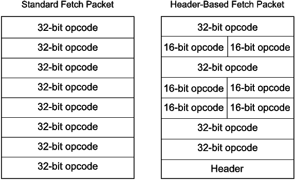
Figure 17 shows the layout of the fetch packet header. The predicate field used to signify a fetch packet header occupies four bits (bits 28-31). There are seven layout bits (bits 21-27) that designate whether the corresponding word in the fetch packet is a 32-bit instruction or a pair of 16-bit instructions. Bits 0-13 are p-bits for 16-bit instructions. For a 32-bit instruction, the corresponding two p-bits in the header are not used (set to 0). The remaining seven expansion bits (bits 14-20) are used to specify different variations of the 16-bit instruction set.
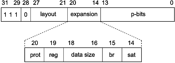
The expansion bits and p-bits are effectively extra opcode bits that are attached to each instruction in the fetch packet. Certain branch instructions appearing in header-based fetch packets can reach half-word program addresses. The compressor software (discussed below) ensures that branch instructions can reach intended destination addresses and encodes the expansion bits to maximize the number of instructions in a fetch packet.
The protected load instruction bit (bit 20) indicates whether all load instructions in the fetch packet are protected. This eliminates the NOP that often occurs after a load instruction in control-oriented code. The register set bit (bit 19) indicates which set of eight registers is used for three operand 16-bit instructions. The data size field (bits 16-18) encodes the access size (byte, half-word, word, double-word) of all 16-bit load and store instructions. The branch bit (bit 15) controls whether branch instructions or certain S-unit arithmetic and shift instructions are available. Finally, the saturation bit (bit 14) indicates whether basic arithmetic operations saturate on overflow and underflow. If the result of an arithmetic operation overflows, then the result saturates to a maximum value, and if an operation underflows, it saturates to a minimum value.
The instruction set extensions also include a new 32-bit CALLP instruction. Unlike branch instructions, where the five delay slots must be filled with other instructions or NOPs, the CALLP instruction is protected, meaning other instructions cannot start in the delay slots of the CALLP. The use of this CALLP can reduce code size up to 6% on some applications (3), with only a small degradation in performance.
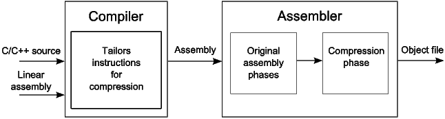
An instruction’s size is determined at assembly-time. (This is possible because each 16-bit instruction has a 32-bit counterpart.) The compressor runs after the assembly phase and is responsible for converting as many 32-bit instructions as possible to equivalent 16-bit instructions. As shown in Figure 18, the compressor takes a specially instrumented object file (where all instructions are 32-bit), and produces an object file where some instructions have been converted to 16-bit instructions.
Compression is an iterative process consisting of one or more compression iterations (3). In each compression iteration, the compressor starts at the beginning of the section’s instruction list and generates new fetch packets until all instructions are consumed. Each new fetch packet may contain eight 32-bit instructions (a regular fetch packet), or contain a mixture of 16- and 32-bit instructions (a header-based fetch packet).
The compressor must select an overlay, which is an expansion bit combination used for a fetch packet that contains 16-bit instructions. There are several expansion bits in the fetch packet header that indicate how the 16-bit instructions in the fetch packet are to be interpreted. For each new fetch packet, the compressor selects a window of instructions and records for each overlay which instructions may be converted to 16-bit. It then selects the overlay that packs the most instructions in the new fetch packet.
During a compression iteration, there is often a potential 16-bit instruction with no other 16-bit instruction immediately before or after. In this case, the compressor may swap instructions within an execute packet to create a pair. Because the C6X compiler often produces execute packets with multiple instructions, swapping instructions within an execute packet increases the conversion rate of potential 16-bit instructions. The compressor does not swap or move instructions outside of execute packets, nor change registers of instructions in order to improve compression. The compressor will always converge on a solution, typically after five or fewer compression iterations (3).
The compressor has the responsibility for packing instructions into fetch packets. The compiler does not make the final decision whether an instruction will become a 16-bit instruction. It does, however, specialize instructions so that they are likely to become 16-bit instructions. We call such instruction specialization tailoring. Because instructions tailored to be 16-bit are restricted to use a subset of the register file and functional units, they can degrade performance. Therefore, the compiler implements a set of command-line options that allow users to control the aggressiveness of the tailoring optimizations. The compiler implements instruction tailoring via the following techniques:
- Instruction selection: The compiler tailors instructions to have a high probability of becoming 16-bit instructions (3). The compiler will replace a single 32-bit instruction with two instructions that will likely compress to two 16-bit instructions. Since 16-bit instructions must be paired in the compressor, replacing a 32-bit instruction with two potential 16-bit instructions reduces the impact of 32-bit alignment restrictions, which improves the compression of the surrounding instructions. When compiling for minimum code size, the compiler attempts to generate instructions that have 16-bit formats only. The compiler assumes that any potential 16-bit instruction will ultimately become 16-bit in the compressor.
- Tiered register allocation: The compiler implements a register allocation scheme that maximizes the usage of the 16-bit instructions’ register file subset (20). Using tiered register allocation, the compiler limits the available registers for operands in potential 16-bit instructions to the 16-bit instructions’ register file subset. If the register allocation attempt succeeds, the operands in potential 16-bit instructions are allocated registers from the 16-bit instructions’ register file subset. If the register allocation attempt fails, the compiler incrementally releases registers for allocation from the rest of the register file for the operands of potential 16-bit instructions. Should register allocation attempts continue failing, the whole register set is made available for all instruction operands thereby falling back on the compiler’s traditional register allocation mechanism.
- Function call customization: To better utilize the 16-bit instructions, the compiler identifies call sites with potential 16-bit instruction operands that have live ranges across the call. The call is then rewritten as an indirect call to a run-time support routine, which takes the address of the original call site function as an operand. The run-time support routine saves the 16-bit instructions’ register file subset on the stack. Control is then transferred to the actual function that was being called at that call site. The called function returns to the run-time support routine, which restores the 16-bit instructions’ register file subset and then returns to the original call site. This technique effectively simulates changing the calling convention to include the 16-bit instructions’ register file subset in the set of registers saved by a called function (21). Calling convention customization is used only when compiling to aggressively minimize code size.
The section summarizes, for each generation of C6X processors, the progressive code size reduction and performance impact of software-pipelined loop collapsing, NOP compression, variable length instructions, and the modulo loop buffer.
The 84 benchmarks used for this analysis are organized into the groups enumerated below. The EEMBC telecom, automotive, and networking groups are taken directly from the EEMBC-v1 embedded benchmark suite (22).
- EEMBC telecom: signal processing loop kernels typically found in telecommunication applications.
- EEMBC automotive: control functions found in automotive engine applications.
- EEMBC networking: packet processing algorithms taken from network and communication infrastructure applications.
- DSP codecs: voice compression decoder/encoders (codecs) used in wireless communication applications including: evrc, g723.1, g729, gsmAMR, gsmefr, gsmfr, gsmhr, Reed-Solomon, modem, trau, and wbamr.
- Multimedia codecs: image, video, music and data compression codecs including: jpeg, mpeg4, mp3, ac3, aes, and des.
- Control code: tcpip, zlib, and hard-disk drive.
- Other applications: miscellaneous benchmarks such as drhystones, dijkstra, susan, and others.
The benchmarks were compiled with the TI C6X compiler version 6.0.8. The C6X compiler has a speed-or-size option that determines how the compiler makes tradeoffs between optimizing for code size or performance. The three speed-or-size options used in this analysis are:
- Size: aggressively minimize code size at the expense of performance.
- Size and speed: minimize code size with nominal impact on performance.
- Speed: aggressively maximize performance at the expense of code size (default).
The compiler provides options to select the processor generation and to disable optimization passes that target specific processor features. For the following results, the baseline configuration is the C6X-1 generation processor compiled with software-pipelined loop collapsing disabled and the speed-or-size option set to speed. All results are normalized to this baseline configuration. Benchmark code size reduction and speedup (performance improvement) are measured on the following four configurations:
- C6X-1(SLC): C6X-1 generation processors with software-pipelined loop collapsing enabled.
- C6X-2(NC): C6X-2 generation processors with NOP compression.
- C6X-3(VLI): C6X-3 generation processors with variable length instructions enabled.
- C6X-3(VLI+MLB): C6X-3 generation processor with both variable length instructions and the modulo loop buffer enabled.
The differences in the benchmark results for the C6X-1(SLC), C6X-2(NC), and C6X-3(VLI+MLB) configurations correspond to the improvements that are seen when upgrading to new processor generations. The C6X-3(VLI) configuration is provided to differentiate the impact of variable length instructions and the modulo loop buffer.
For the most part, the configurations accumulate (i.e., C6X-3(VLI+MLB) is really C6X-3(NC+SLC+VLI+MLB). One exception is the overlap between SLC and MLB since both are minimizing the code size of software-pipelined loops. Software-pipelined loops that do not use the MLB still benefit from loop collapsing.
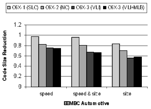
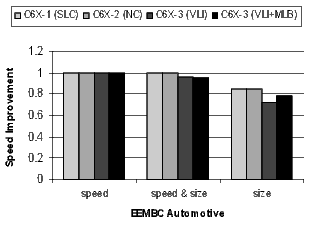
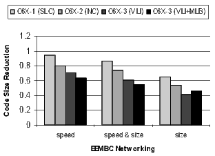
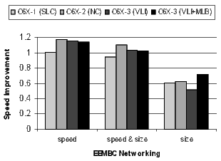
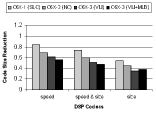
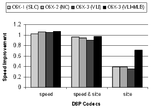
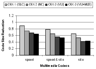
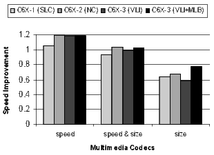
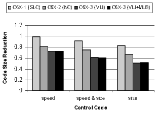
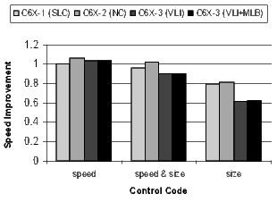
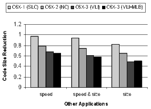
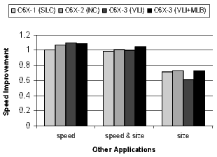
For each configuration, Figures 19, 20, 21, and 22 present the normalized average code size reduction and speed improvement (the y-axis). For code size reduction, smaller is better, and for speed improvement, larger is better. Each configuration is compiled for all three speed-or-size options (the x-axis).
Figure 19 summarizes the results for all benchmarks relative to C6X-1 compiled for speed with no loop collapsing. The results are averages across all benchmarks. Recall that because the compiler is disabling optimizations that increase code size, performance will degrade at the speed&size and size options. The goal is to minimize the degradation as much as possible.
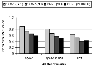
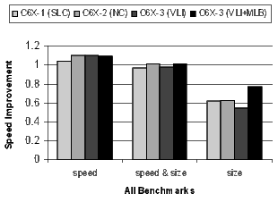
The following analysis of the results in Figure 19 is grouped by compiler speed-or-size option.
- Speed:
- C6X-1(SLC): The 3.7% speedup improvement is from the elimination of compensation code around software-pipelined loops. Software pipelined loop collapsing improves code size by 9%.
- C6X-2(NC): The 10.4% speedup is predominately from increasing the size of the register file. NOP compression has more than doubled the code-size reduction to 24.9%.
- C6X-3(VLI): Some of the compiler transformations that exploit the variable length instructions degrade the performance slightly from 10.0% to 10.4%. The variable length instructions drop the average code-size reduction from 24.9% to 33.3%.
- C6X-3(VLI+MLB): Some of the restrictions on using the MLB have degraded performance slightly further to 9.4%. The code-size reduction has reached an impressive 40%.
- Speed and Size:
- C6X-1(SLC): A speedup degradation of 2.9% and a code-size reduction of 17.6%.
- C6X-2(NC): The 1.4% speedup improvement is from the larger register file. NOP compression has almost doubled the code-size reduction to 32%.
- C6X-3(VLI): Compiler transformations to exploit variable length instructions have degraded the speedup by 2.6%, but the code-size reduction has improved to 43%.
- C6X-3(VLI+MLB): The 0.8% speedup is because the modulo loop buffer allows the compiler to aggressively software pipeline loops even when compiling for size. The code-size reduction has increased to an impressive 47.3%.
- Size:
- C6X-1(SLC): A large code-size reduction of 35.4% with performance degrading by 38.1%.
- C6X-2(NC): A large code-size reduction of 47.1% with a slight improvement in the performance degradation to -37.0
- C6X-3(VLI): A very large code-size reduction of 58.2% with performance degrading by a huge 45.2%. Variable length instructions can reduce code size significantly, but the compiler transformations that enable them are costly in terms of performance.
- C6X-3(VLI+MLB): An impressive code-size reduction of 56.1% with only a 22.5% performance degradation. The modulo loop buffer enables the compiler to software pipeline loops even when compiling for code size only.
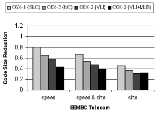
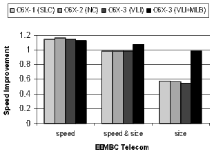
Figure 20 shows the results for the EEMBC telecom, automotive, and networking benchmarks. These benchmarks are smaller and representative of code in specific application spaces. The automotive benchmarks are dominated by control code, the telecom code is primarily loop-oriented, and the networking algorithms are a mixture of control- and loop-oriented code. Note that when compiling the C6X-3(VLI+MLB) configuration for speed, there is a 57% code-size reduction in the telecom benchmarks.
The results for the DSP codecs, multimedia codecs, control code, and other applications are shown in Figures 21 and 22. Many of these benchmarks are complete applications. The DSP and multimedia codecs are loop-oriented applications, the control code is obviously control-oriented, and the other applications are a mixture both. Note the 44.3% code-size reduction in the DSP codecs when compiling the C6X-3(VLI-MLB) configuration for speed.
There is a distinct difference in the results between control- and loop-oriented benchmarks. The loop-oriented benchmarks are demonstrating more code size reduction. Clearly, software-pipelined loop collapsing and the modulo loop buffer are going to have no effect on the size of control-oriented code. However, variable length instructions and NOP compression improve both loop- and control-oriented code.
The variable length instructions create a more significant size and performance tradeoff range. When a programmer’s primary desire is to control code size, this additional range can be useful in balancing performance and code size in a memory-constrained application, which is common in embedded systems.
Code size is a primary concern in the embedded computing community. Minimizing physical memory requirements reduces total system cost, improves system performance by allowing more code to fit in on-chip memory and program caches, and improves power efficiency.
We have presented the co-design of the following four compiler optimizations and architecture features, which reduce code size across three generations of the C6X processor:
- Software-pipelined loop collapsing: a compiler technique that reduces the code size of software-pipelined loops.
- NOP compression: a hardware technique that compresses the encoding of padding and pipeline NOP instructions.
- Variable length instructions: complementary compiler and hardware techniques that encode commonly occurring 32-bit instructions as 16-bit instructions.
- Modulo loop buffer: a hardware technique to reduce the code size and power efficiency of software-pipelined loops.
We presented the code-size reduction and performance impact of using these techniques to compile a set of 84 benchmarks. With the compiler’s speed-or-size option set to maximize speed, the results showed an impressive cumulative average code size reduction of 40%.
The FPS-164 attached array processor (23, 24) was a horizontally microcoded computer used for scientific applications, such as signal processing. In the early 1980’s Fisher and his coworkers in the ELI (Enormously Long Instructions) project at Yale University developed the concepts of VLIW architectures (25). The ELI project developed into Multiflow Corporation and the Trace family of computers (26). The significant impact of the ELI project was the development of a hardware and compiler strategy at the same time. The architecture relied heavily on a trace scheduling compiler. The Trace compiler did not use software pipelining, but instead used extensive loop unrolling. The Trace Family of computers was available in three sizes where each size replicated a cluster. There were one-, two-, and four-cluster machines.
The Cydra 5 computer developed at Cydrome Inc. (27, 28) evolved from the polycyclic architecture described in (13). The Cydra 5 architecture was a VLIW system that was designed for optimizing the execution of inner loops using software pipelining. As with the Trace computer, the Cydra 5 relies on the compiler to statically schedule (29) all operations. The Warp architecture is a systolic array consisting of 10 VLIW cell processors (30, 31).
The Intel Itanium IA-64 processor (32) is a VLIW design, although Intel refers to it as an explicitly parallel instruction computing (EPIC) processor. Today (in 2010), the VLIW philosophy is popular in embedded processors. Besides the C6X, other examples of embedded VLIW processors include the Analog Devices SHARC DSP (33), the Trimedia ST200 (34), the Infineon Carmel (35) and, Tensilica’s Xtensa LX2 (36).
Another approach to reduce code size is to store a compressed image of the VLIW program code in external memory and to use run-time software or hardware to decompress the code as it is executed or loaded into a program cache (37, 38). Other approaches have used variable length instruction encoding techniques to reduce the size of execute packets (2). Finally, some embedded processors have modes that implement smaller opcode encodings for a subset of frequently occurring instructions. Examples of mode-based architectures are the ARM architecture’s Thumb mode (39, 40) and the MIPS32 architecture’s MIPS16 mode (41).
The basic concepts of a modulo loop buffer are described by Merten and Hwu (18). Other approaches to reduce the code size of software-pipelined loops employ special-purpose hardware. Instructions from different iterations are controlled by distinct rotating predicates (42). Loop-control instructions are used in combination with the rotating predicate register file to conditionally nullify a subset of the instructions during the pipe-fill and pipe-drain phases, eliminating the need for explicit prologs and epilogs. Only the kernel code is explicitly represented. The advantage of kernel-only code is that there is no code growth. The disadvantage is that the prolog and epilog code can neither be customized nor overlapped with surrounding instructions. The effects of software-pipelined loop collapsing are similar to kernel-only code, but software-pipelined loop collapsing does not require hardware support beyond the availability of static predicate registers.
(1) J. A. Fisher, P. Faraboschi, and C. Young, Embedded Computing : A VLIW Approach to Architecture, Compilers and Tools. Morgan Kaufmann, December 2004.
(2) S. Aditya, S. A. Mahlke, and B. R. Rau, “Code size minimization and retargetable assembly for custom EPIC and VLIW instruction formats,” ACM Transactions on Design Automation of Electronic Systems, vol. 5, no. 4, pp. 752–773, 2000.
(3) T. T. Hahn, E. J. Stotzer, D. Sule, and M. Asal, “Compilation strategies for reducing code size on a VLIW processor with variable length instructions,” in HiPEAC, 2008, pp. 147–160.
(4) TMS320C6000 Optimizing Compiler User’s Guide, spru187o ed., Texas Instruments, Inc., May 2008.
(5) A. V. Aho, R. Sethi, and J. D. Ullman, Compilers: Principles, Techniques, and Tools. Boston, MA, USA: Addison-Wesley Longman Publishing Co., Inc., 1986.
(6) R. Allen and K. Kennedy, Optimizing Compilers for Modern Architectures. San Francisco, CA, USA: Morgan Kaufman Publishers Inc., 2002.
(7) K. Cooper and L. Torczon, Engineering a Compiler. San Francisco, CA, USA: Morgan Kaufman Publishers Inc., 2003.
(8) S. S. Muchnick, Advanced Compiler Design and Implementation. San Francisco, CA, USA: Morgan Kaufmann Publishers Inc., 1997.
(9) E. J. Stotzer, E. D. Granston, and A. S. Ward, “Methods and apparatus for reducing the size of code with an exposed pipeline by encoding NOP operations as instruction operands,” U.S. Patent 6,799,266, September 2004.
(10) A. L. Davis, R. H. Scales, N. Seshan, E. J. Stotzer, and R. E. Tatge, “Microprocessor with an instruction immediately next to a branch instruction for adding a constant to a program counter,” U.S. Patent 6,889,320, May 2005.
(11) E. J. Stotzer and E. L. Leiss, “Instruction encoding schemes that reduce code size on a VLIW processor,” in CLEI ’10: Proceedings of the Conferencia Latinoamericana de Informï¿ tica, October 2010.
(12) E. D. Granston, J. Zbiciak, and E. J. Stotzer, “Method for software pipelining of irregular conditional control loops,” U.S. Patent 6,892,380, May 2005.
(13) B. R. Rau and C. D. Glaeser, “Some scheduling techniques and an easily schedulable horizontal architecture for high performance scientific computing,” in MICRO 14: Proceedings of the 14th Annual Workshop on Microprogramming. Piscataway, NJ, USA: IEEE Press, 1981, pp. 183–198.
(14) E. J. Stotzer and E. L. Leiss, “Modulo scheduling without overlapped lifetimes,” in LCTES ’09: Proceedings of the 2009 ACM SIGPLAN/SIGBED Conference on Languages, Compilers, and Tools for Embedded Systems. New York, NY, USA: ACM, 2009, pp. 1–10.
(15) E. Granston, R. Scales, E. Stotzer, A. Ward, and J. Zbiciak, “Controlling code size of software-pipelined loops on the TMS320C6000 VLIW DSP architecture,” in MSP-3: Proceedings of the 3rd IEEE/ACM Workshop on Media and Streaming Processors, 2001, pp. 29–38.
(16) M. Jayapala, F. Barat, T. Vander Aa, F. Catthoor, H. Corporaal, and G. Deconinck, “Clustered loop buffer organization for low energy VLIW embedded processors,” IEEE Transactions on Computing, vol. 54, no. 6, pp. 672–683, 2005.
(17) E. J. Stotzer and E. L. Leiss, “Compiler and hardware support for reducing the code size of software pipelined loops,” in CLEI ’11: Proceedings of the Conferencia Latinoamericana de Informï¿ tica, October 2011.
(18) M. C. Merten and W.-m. W. Hwu, “Modulo schedule buffers,” in MICRO 34: Proceedings of the 34th Annual ACM/IEEE International Symposium on Microarchitecture. Washington, DC, USA: IEEE Computer Society, 2001, pp. 138–149.
(19) M. Asal, E. Stotzer, and T. Hahn, “VLIW optional fetch packet header extends instruction set space,” U.S. Patent 7,673,119, March 2010.
(20) D. Sule, E. Stotzer, and T. Hahn, “Tiered register allocation,” U.S. Patent App. 20070022413, January 2007.
(21) D. Sule and E. Stotzer, “Technique for the calling of a sub-routine by a function using an intermediate sub-routine,” U.S. Patent App. 20070016899, January 2007.
(22) EEMBC, The Embedded Microprocessor Benchmark Consortium. (Online). Available: http://www.eembc.org
(23) A. Charlesworth, “An approach to scientific array processing: The architectural design of the AP-120B/FPS-164 family,” IEEE Computer, vol. 14, no. 3, pp. 18–27, 1981.
(24) R. F. Touzeau, “A Fortran compiler for the FPS-164 scientific computer,” in SIGPLAN ’84: Proceedings of the 1984 SIGPLAN Symposium on Compiler Construction. New York, NY, USA: ACM, 1984, pp. 48–57.
(25) J. R. Ellis, Bulldog: A Compiler for VLIW Architectures. Cambridge, MA, USA: MIT Press, 1986.
(26) P. G. Lowney, S. M. Freudenberger, T. J. Karzes, W. D. Lichtenstein, R. P. Nix, J. S. O’Donnell, and J. Ruttenberg, “The multiflow trace scheduling compiler,” Journal of Supercomputing, vol. 7, no. 1-2, pp. 51–142, 1993.
(27) G. R. Beck, D. W. L. Yen, and T. L. Anderson, “The Cydra 5 minisupercomputer: Architecture and implementation,” Journal of Supercomputing, vol. 7, no. 1-2, pp. 143–180, 1993.
(28) J. C. Dehnert, P. Y.-T. Hsu, and J. P. Bratt, “Overlapped loop support in the Cydra 5,” in ASPLOS-III: Proceedings of the Third International Conference on Architectural Support for Programming Languages and Operating Systems. New York, NY, USA: ACM, 1989, pp. 26–38.
(29) J. C. Dehnert and R. A. Towle, “Compiling for the Cydra 5,” Journal of Supercomputing, vol. 7, no. 1-2, pp. 181–227, 1993.
(30) M. S. Lam, A Systolic Array Optimizing Compiler. Norwell, MA, USA: Kluwer Academic Publishers, 1989.
(31) R. Cohn, T. Gross, and M. Lam, “Architecture and compiler tradeoffs for a long instruction wordprocessor,” in ASPLOS-III: Proceedings of the Third International Conference on Architectural Support for Programming Languages and Operating Systems. New York, NY, USA: ACM, 1989, pp. 2–14.
(32) J. Huck, D. Morris, J. Ross, A. Knies, H. Mulder, and R. Zahir, “Introducing the IA-64 architecture,” IEEE Micro, vol. 20, no. 5, pp. 12–23, 2000.
(33) “The SHARC Processor,” Analog Devices Inc. (Online). Available: http://www.analog.com
(34) “The ST200 Processor,” STMicroelectronics Inc. (Online). Available: http://www.st.com
(35) Carmel, “The Carmel DSP processor,” Infineon Technologies AG. (Online). Available: http://www.infineon.com
(36) Xtensa, “Xtensa customizable processors,” Tensilica Inc. (Online). Available: http://www.tensilica.com
(37) C. H. Lin, Y. Xie, and W. Wolf, “LZW-based code compression for VLIW embedded systems,” in DATE ’04: Proceedings of the Conference on Design, Automation and Test in Europe, vol. 3. Washington, DC, USA: IEEE Computer Society, 2004, pp. 76–81.
(38) M. Ros and P. Sutton, “Compiler optimization and ordering effects on VLIW code compression,” in CASES ’03: Proceedings of the 2003 International Conference on Compilers, Architecture and Synthesis for Embedded Systems. New York, NY, USA: ACM Press, 2003, pp. 95–103.
(39) ARM7TDMI (Rev. 4) Technical Reference Manual, ARM Limited, 2001.
(40) R. Phelan, “Improving ARM code density and performance,” ARM Limited, Tech. Rep., 2003.
(41) MIPS32 Architecture for Programmers, Vol. IV-a: The MIPS16 Application Specific Extension to the MIPS32 Architecture, MIPS Technologies, 2001.
(42) B. R. Rau, M. S. Schlansker, and P. P. Tirumalai, “Code generation schema for modulo scheduled loops,” in MICRO 25: Proceedings of the 25th Annual International Symposium on Microarchitecture. Los Alamitos, CA, USA: IEEE Computer Society Press, 1992, pp. 158–169.

